Electric equipment module structure

a technology of electrical equipment and modules, applied in the direction of contact members penetrating/cutting insulation/cable strands, electrical apparatus, fastening/insulating connecting parts, etc., can solve the problems of allophone and vibration wear, the height of the case and the structure is increased, and the plurality of lamps is difficult to arrange in the same direction

Inactive Publication Date: 2006-10-05
YAZAKI CORP
View PDF6 Cites 4 Cited by
  • Summary
  • Abstract
  • Description
  • Claims
  • Application Information

AI Technical Summary

Benefits of technology

[0019] The above-mentioned constitution demonstrates an action and an effect same as the lamp module to the electric equipment module described in claim 5. For example, in claim 3, the connection portion of the case of one lamp module engages with the connected

Problems solved by technology

However, the above-mentioned conventional connector module bends the electric wire 55 to a generally crank-shape for strain-relief and causes problems of the increase of the height of the case and the scale of the structure.
Moreover, in the above-mentioned lamp module, when the illumination intensity is not enough with a

Method used


Image

  • Electric equipment module structure
  • Electric equipment module structure
  • Electric equipment module structure

Examples


Embodiment Construction

[0029] The embodiments of the present invention are described with reference to the attached drawings.

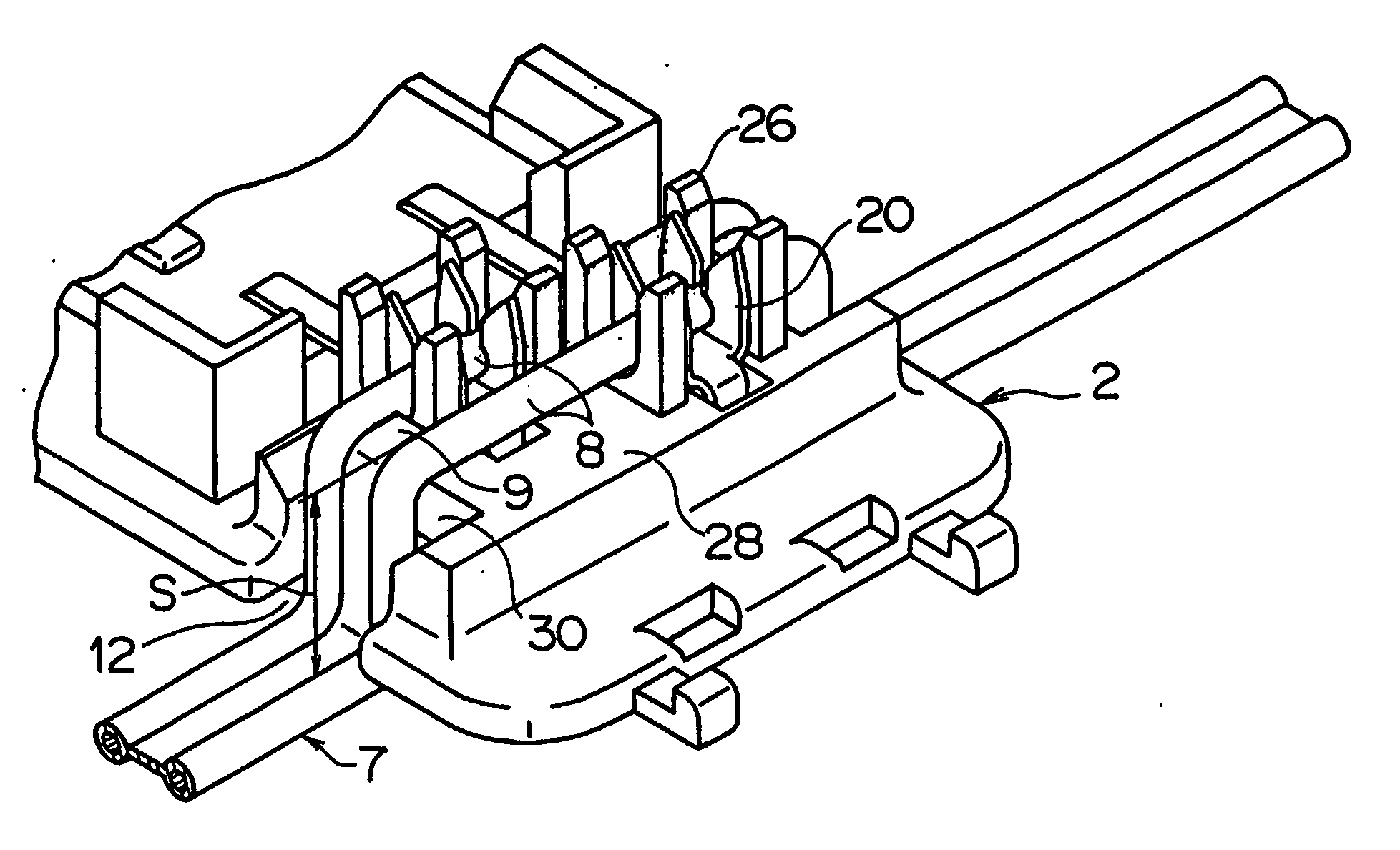
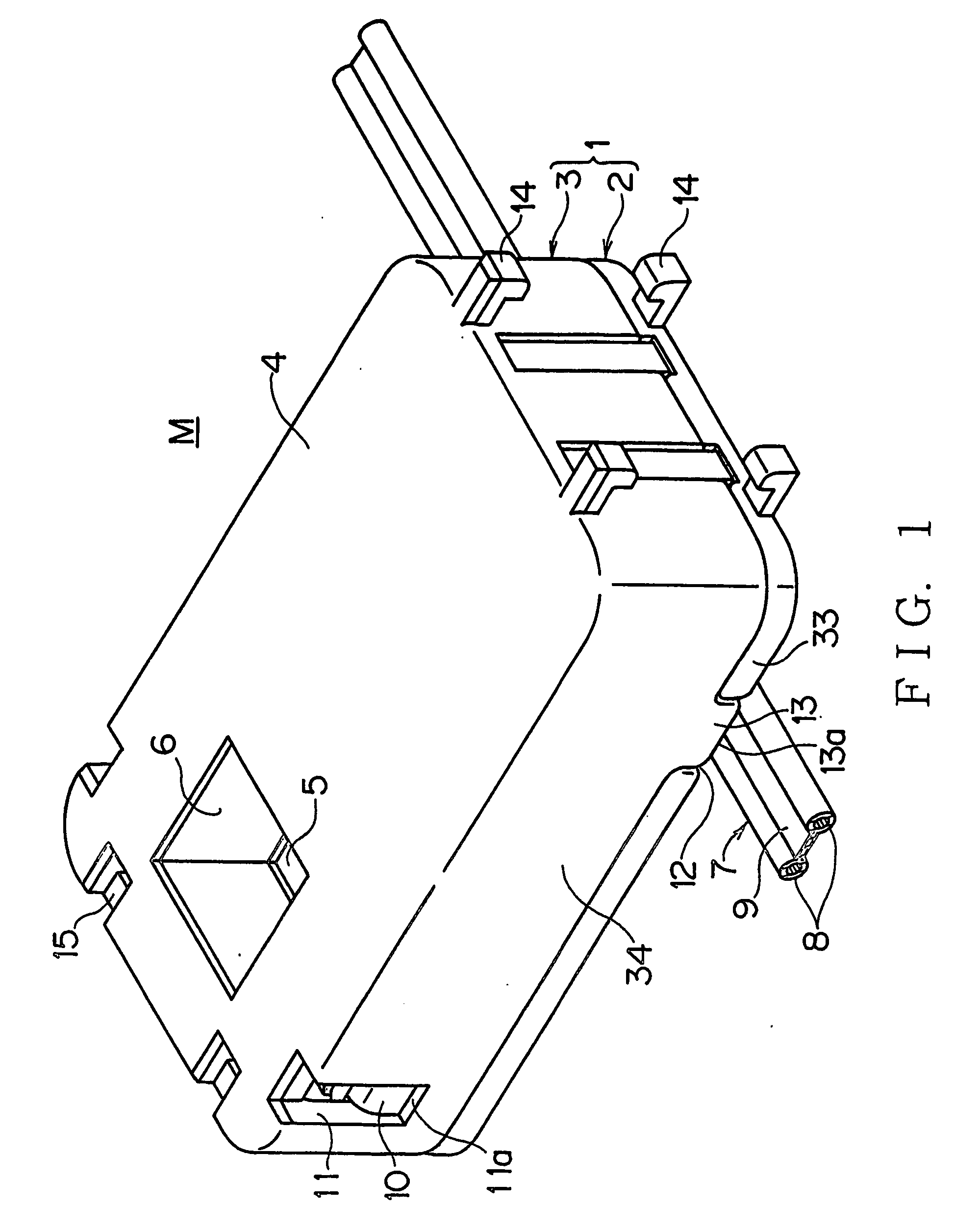
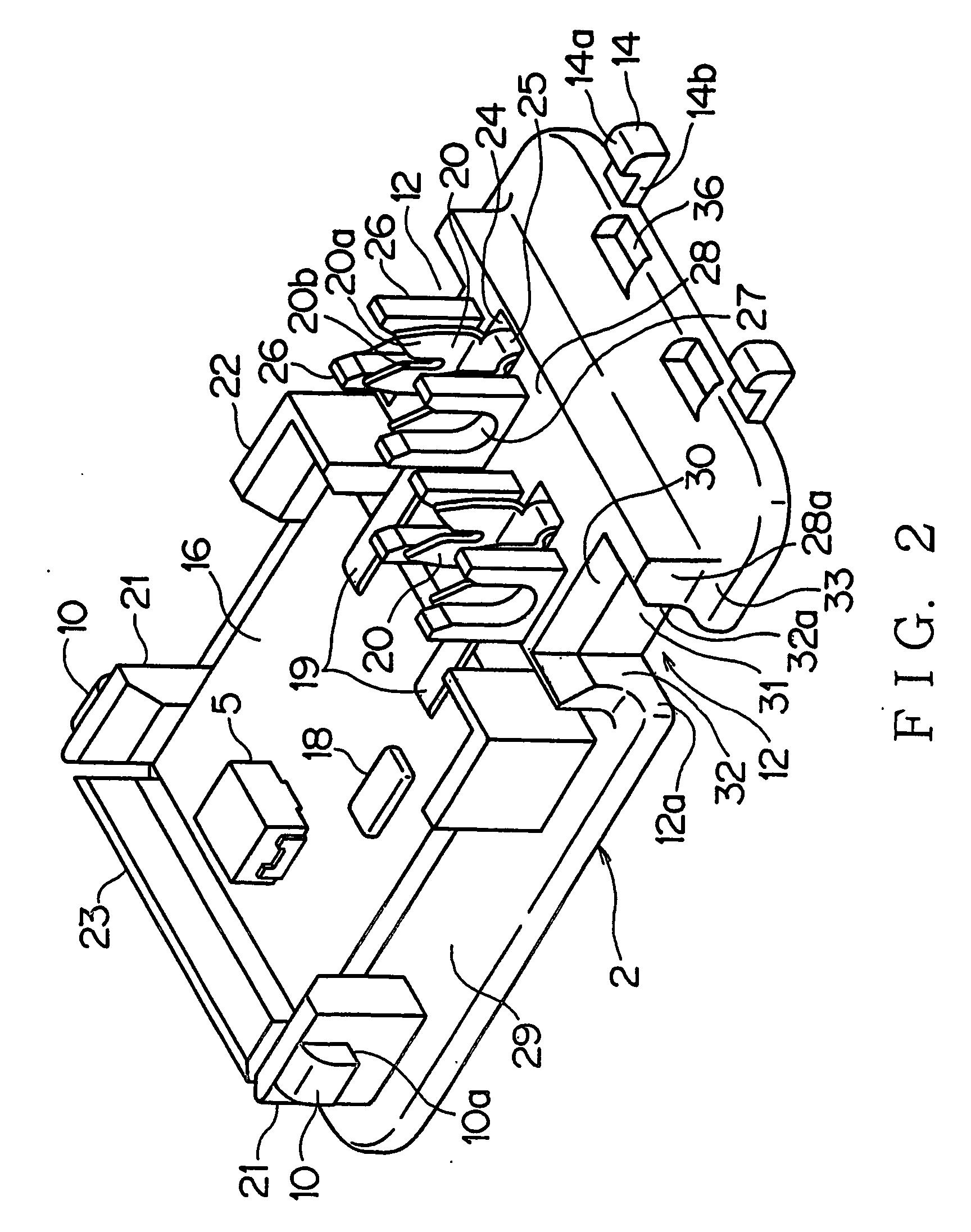
[0030] FIGS. 1 to 5 show an embodiment of a lamp module structure as one of the embodiments of an electric equipment module according to the present invention. FIG. 1 shows the overall view of a case (lamp module), FIG. 2 a base side structure, FIG. 3 an electric wire pressed to the base side, FIG. 4 the structure of a cover, and FIG. 5 the structure of one end side of the case, respectively.

[0031] As shown in FIG. 1, the case 1 made of synthetic (insulation) resin which comprises of the base 2 and the cover 3 is formed in a thin shape of a generally rectangular parallelepiped. A tapered window 6 following a light emitting face of an LED 5 of illuminant (Light Emitting Diode as illuminant) is formed in a top wall 4 of the cover 3, a flat cable 7 is wired in a crossing direction in the case 1 at the opposite end side of the window 6.

[0032] The base 2 and the cover 3 are mutually l...


PUM


Abstract

A case 1 comprises a base 2 and a cover 3, a terminal is disposed in the case, an electric wire 8 connected to the terminal is arranged in the base, a cutout portion 12 to bend and guide out the electric wire is penetrated and formed in the base 2, and an electric equipment module structure in which the outside opening of the cutout portion is closed by the cover is adopted. A projection 13 pressing the electric wire 8 in the cutout portion 12 is formed in the cover 3, and the electric wire is bent along with the projection 13. The base 2 and cover 3 have a connection portion 14 at the end, and have a connected portion 15 at the other end, respectively, and a plurality of cases 1 can be connected mutually. The connection portion 14 biases the base 2 and cover 3 in the closing direction.

Description

TECHNICAL FIELD OF THE INVENTION [0001] This invention relates to the electric equipment module structure which provides a strain-relief function to electric wire for supplying electric power, such as to illuminant, and raises the usability of lamp module etc. capable of a plurality of connections. BACKGROUND ART [0002] Various forms of lamp module have been conventionally proposed as for internal lighting in the ceiling of vehicles etc. Connector module attached in the trim of a ceiling etc. for connecting the circuit of the ceiling side is also proposed. [0003]FIG. 9 shows a sun visor connector 51 as an example previously proposed by this applicant, provided with a case comprising a base 52 and cover 53 made of a synthetic resin, a pressure contact terminal 54 arranged at the base 52. An electric wire 55 is wired in bent to the U-shape above and below of the base 52 and the cover 53. The sun visor connector 51 is fixed to the trim of the ceiling, the connector of the sun visor bei...

Claims


Application Information

Patent Timeline
IPC IPC(8): H01R4/24H02G3/38
CPCH01R12/675
Inventor CHIBA, SHINGOMATSUSHITA, HARUYUKI
Owner YAZAKI CORP
Why Eureka
Try Eureka