Optional telemetry antenna for implantable medical devices

Inactive Publication Date: 2006-10-05
DUBLIN GARRY L +3
View PDF10 Cites 36 Cited by
  • Summary
  • Abstract
  • Description
  • Claims
  • Application Information

AI Technical Summary

Benefits of technology

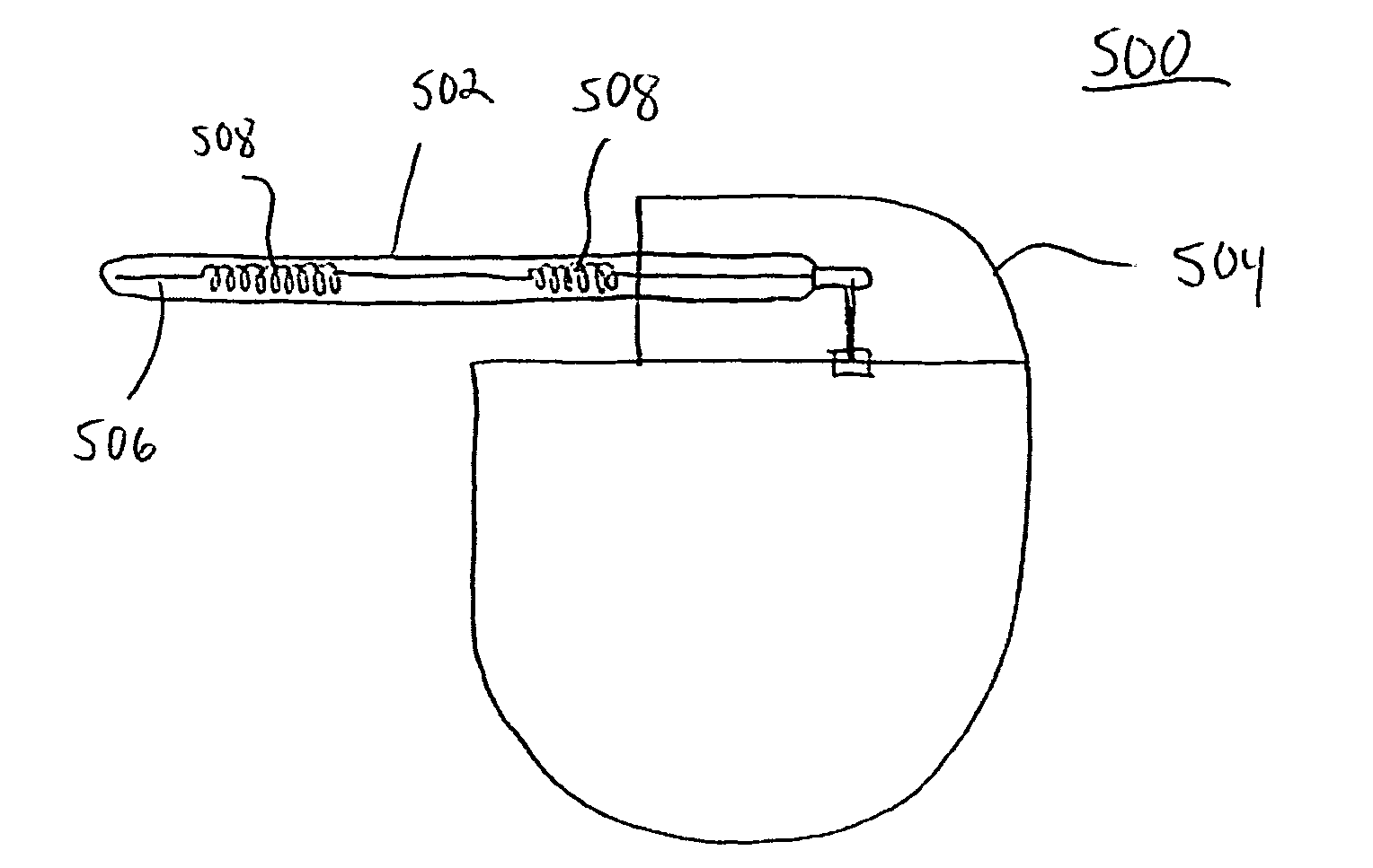
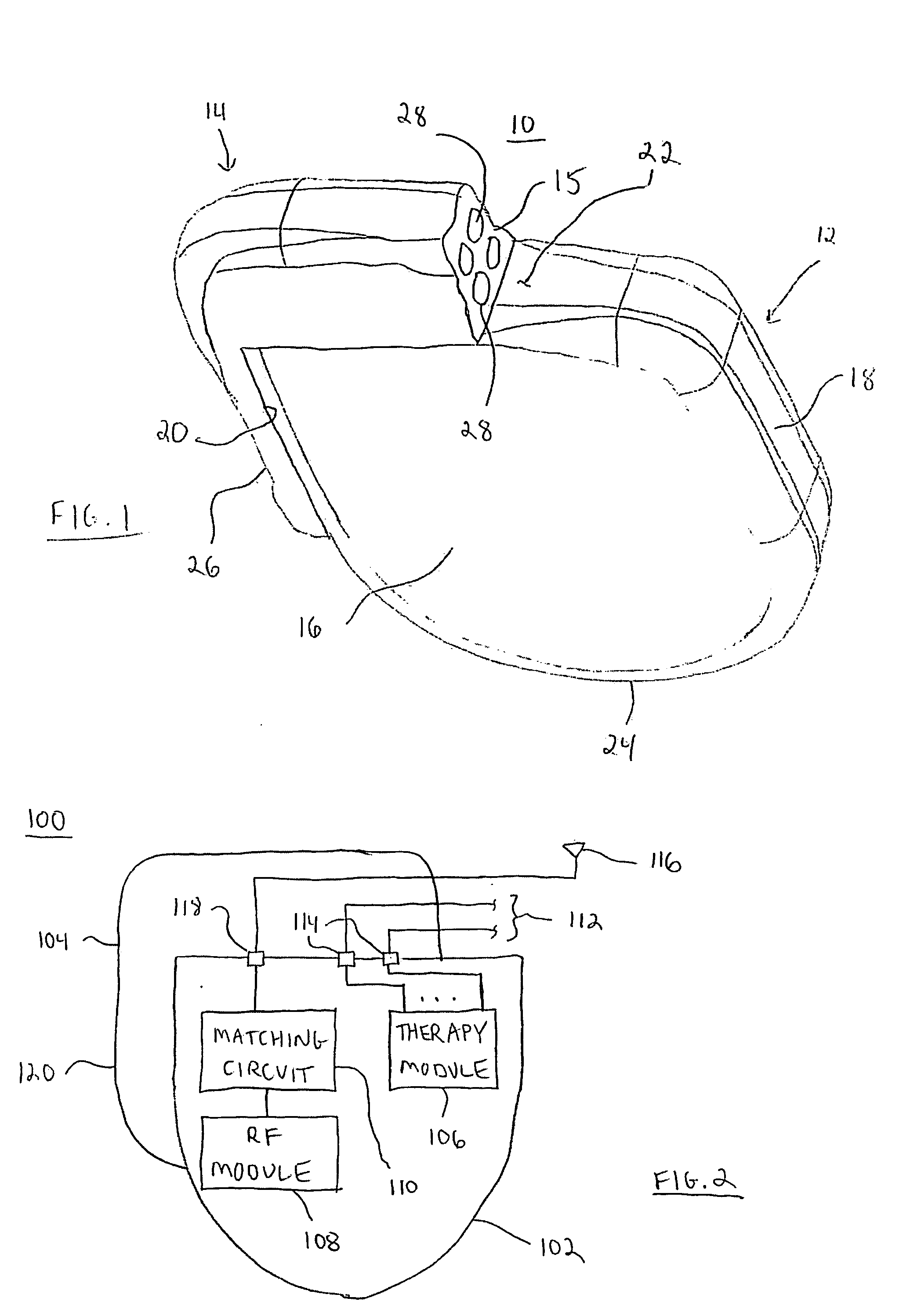
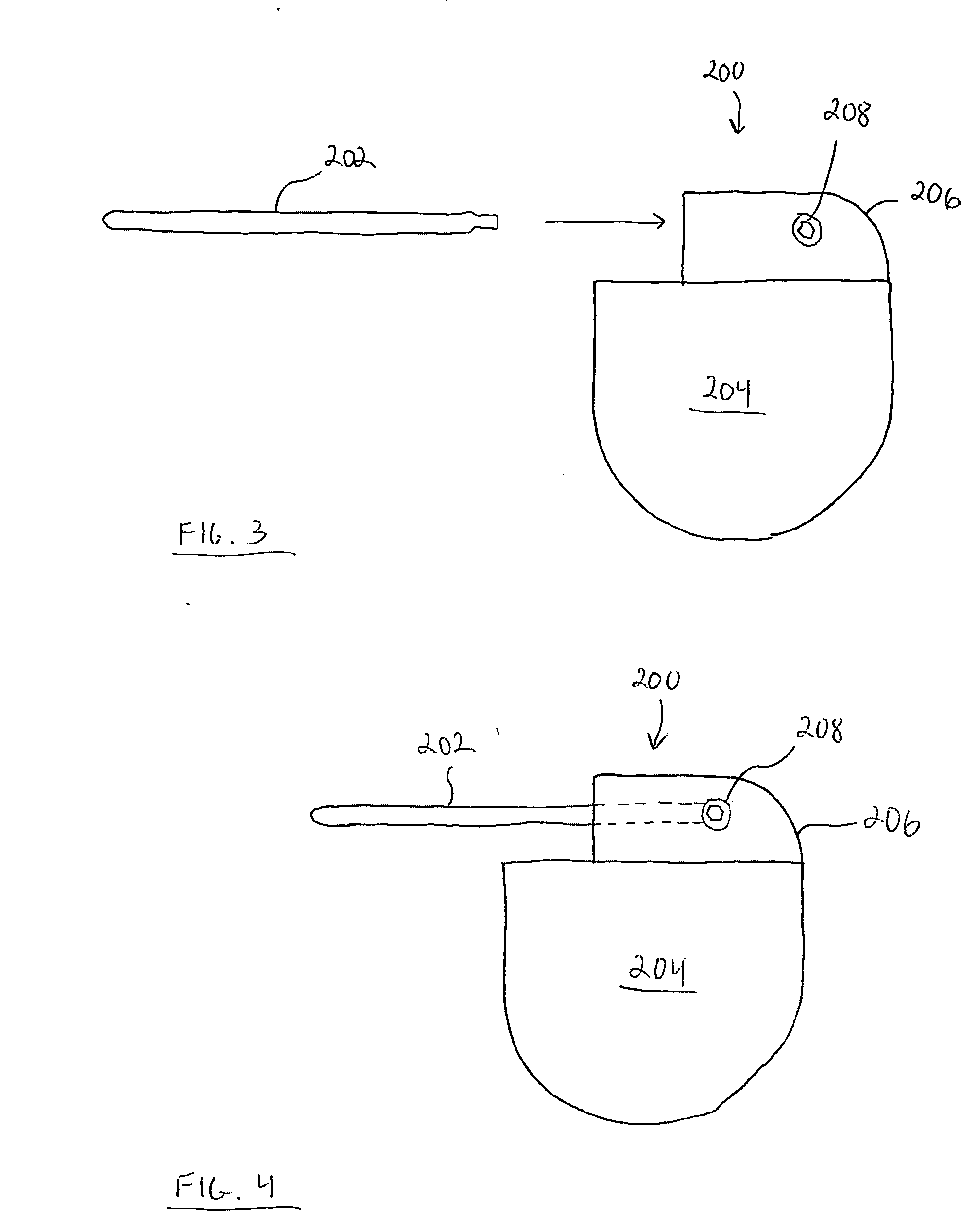
[0008] An IMD configured in accordance with an embodiment of the invention includes an optional telemetry antenna having a connection end that is secured within the header block of the IMD. The optional telemetry antenna may be employed in addition to a “fixed” antenna element, such as an antenna element that is encapsulated within the header block, or it may serve as the only antenna element for the IMD. The specific configuration, RF characteristics, antenna gain, and other operational features of the optional a

Problems solved by technology

As the technology has advanced, IMDs have become more complex in possible programmable operating modes, menus of available operating parameters, and capabilities of monitoring, which in turn increase the variety of possible physiologic conditions and electrical signals handled by the IMD.
Consequently, such increasing complexity places increasing demands on the programming system.
Generally, the IMD antenna is disposed within the hermetically sealed housing; however, the typically conductive housing adversely attenuates the radiated RF field and limits the data transfer distance between the programmer head and the IMD RF telemetry anten

Method used


Image

  • Optional telemetry antenna for implantable medical devices
  • Optional telemetry antenna for implantable medical devices
  • Optional telemetry antenna for implantable medical devices

Examples


Embodiment Construction

[0020] The following detailed description is merely illustrative and is not intended to limit the invention or the application and uses of the invention. Furthermore, there is no intention to be bound by any expressed or implied theory presented in the preceding technical field, background, brief summary or the following detailed description.

[0021] The following description refers to components or features being “connected” or “coupled” together. As used herein, unless expressly stated otherwise, “connected” means that one component / feature is directly or indirectly connected to another component / feature, and not necessarily mechanically. Likewise, unless expressly stated otherwise, “coupled” means that one component / feature is directly or indirectly coupled to another component / feature, and not necessarily mechanically. Thus, although the figures may depict example arrangements of elements, additional intervening elements, devices, features, or components may be present in an actu...


PUM


Abstract

An implantable medical device (“IMD”) configured in accordance with an example embodiment of the invention generally includes a housing, a connector header block coupled to the housing, and an optional telemetry antenna coupled to the header block. The optional antenna assembly is suitably configured to support the intended IMD application (e.g., the desired telemetry range, the intended IMD implant location, or other practical considerations). The optional antenna assembly may be utilized by itself or in cooperation with a permanent telemetry antenna of the IMD. In one practical embodiment, the optional antenna assembly has a connection end that is compliant with known pacemaker electrode lead standards, which allows the IMD to leverage existing connection methodologies.

Description

TECHNICAL FIELD [0001] The present invention relates generally to implantable medical devices (“IMDs”). More particularly, the present invention relates to telemetry antennas suitable for deployment in IMDs. BACKGROUND [0002] The prior art is replete with a variety of IMDs that provide diagnostic and / or therapeutic capabilities. Such IMDs include, without limitation: cardiac pacemakers; implantable cardioverters / defibrillators (“ICDs”); and various tissue, organ, and nerve stimulators or sensors. IMDs typically include functional components contained within a hermetically sealed enclosure or housing, which is sometimes referred to as a “can.” In some IMDs, a connector header or connector block is attached to the housing, and the connector block facilitates interconnection with one or more elongated electrical medical leads. The header block is typically molded from a relatively hard, dielectric, non-conductive polymer having a thickness approximating the thickness of the housing. Th...

Claims


Application Information

Patent Timeline
IPC IPC(8): A61N1/36
CPCA61N1/37229A61N1/3752A61N1/375
Inventor DUBLIN, GARRY L.VILLASECA, EDUARDO H.VERHOEF, WILLIAM D.WALLACE, RODNEY S.
Owner DUBLIN GARRY L
Why Eureka
Try Eureka