
Breast implant

a breast implant and implant technology, applied in the field of breast implants, can solve the problems of breast implants that cannot be maintained, prostheses that cannot, however, rupture, leakage or rupture,

Inactive Publication Date: 2006-10-05
TIAHRT LEIF K
View PDF6 Cites 51 Cited by
  • Summary
  • Abstract
  • Description
  • Claims
  • Application Information

AI Technical Summary

Benefits of technology

[0011] The present invention is directed to a breast prosthesis which may or may not be fluid-filled, and a method for making the breast prosthesis that substantially obviates one or more of the limitations of the related art. To achieve these and other advantages and in accordance with the purpose of the invention, as embodied and broadly described herein, the invention is a soft tissue prosthesis, particularly a breast prosthesis, comprising a self-supporting flexible shell substantially surrounding an interior compartment. An inner surface of the shell has a plurality of flexible protruberances formed thereon that extend radially inwardly into the interior compartment. Preferably, at least a portion of an outer surface of the flexible shell has a rough texture operable for permitting tissue ingrowth into the outer surface of the shell when the breast prosthesis is implanted in a patient (host). The shell and the protuberances are preferably formed as a single body that is unitary ...

Problems solved by technology

Two major problems with prostheses heretofore used is rupture and the lack of maintained projection, particularly in a manner such that the proper shape and location on the chest wall would be achieved and maintained, and the fact that their shape and consistency generally does not match the remaining breast.
The prosthesis can, however, rupture; leaking filler material into the body.
Notwithstanding their advantages, such prior art fluid-filled implants may leak or rupture following implantation with possibly adverse effects on the host.

Method used


Image

  • Breast implant
  • Breast implant
  • Breast implant

Examples


Embodiment Construction

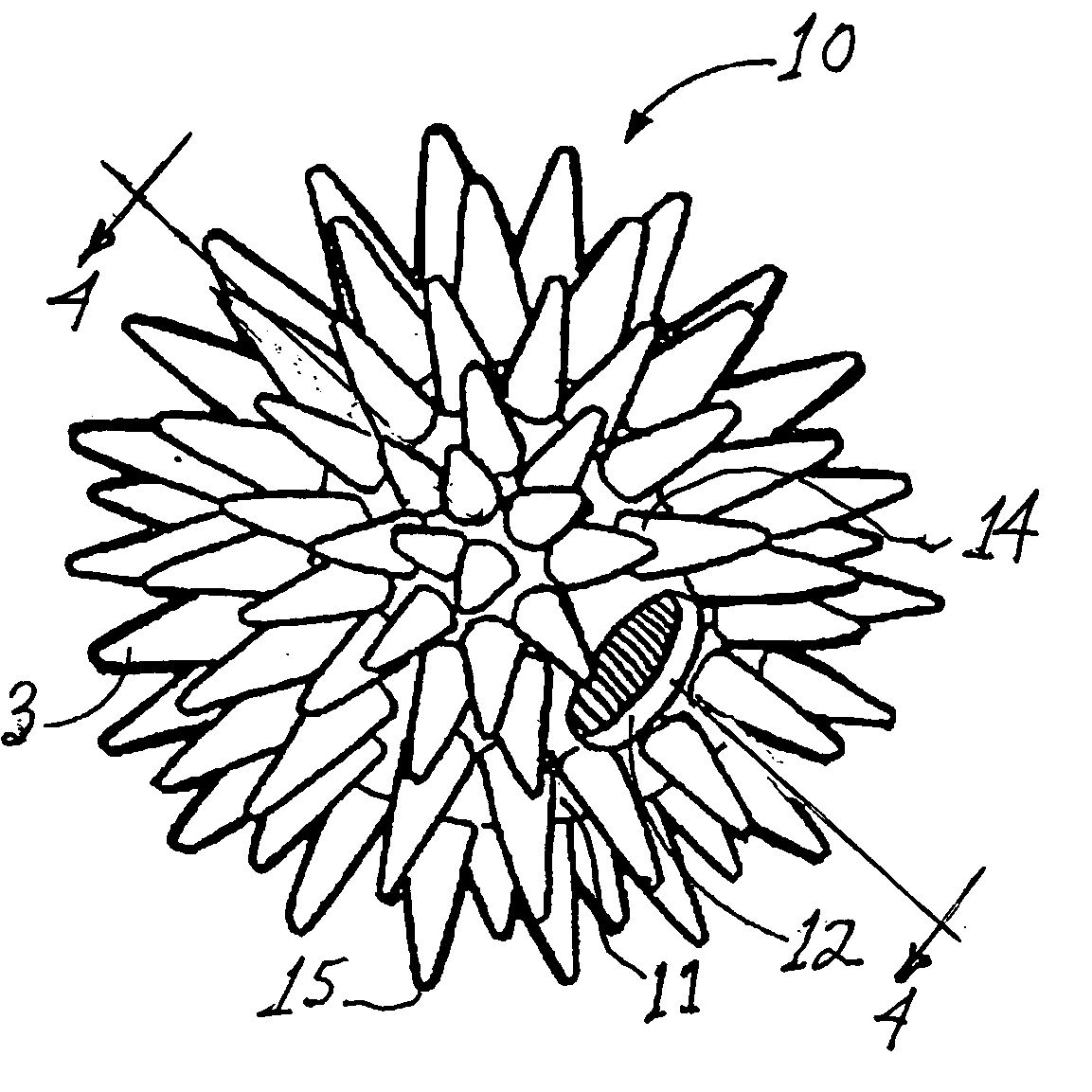
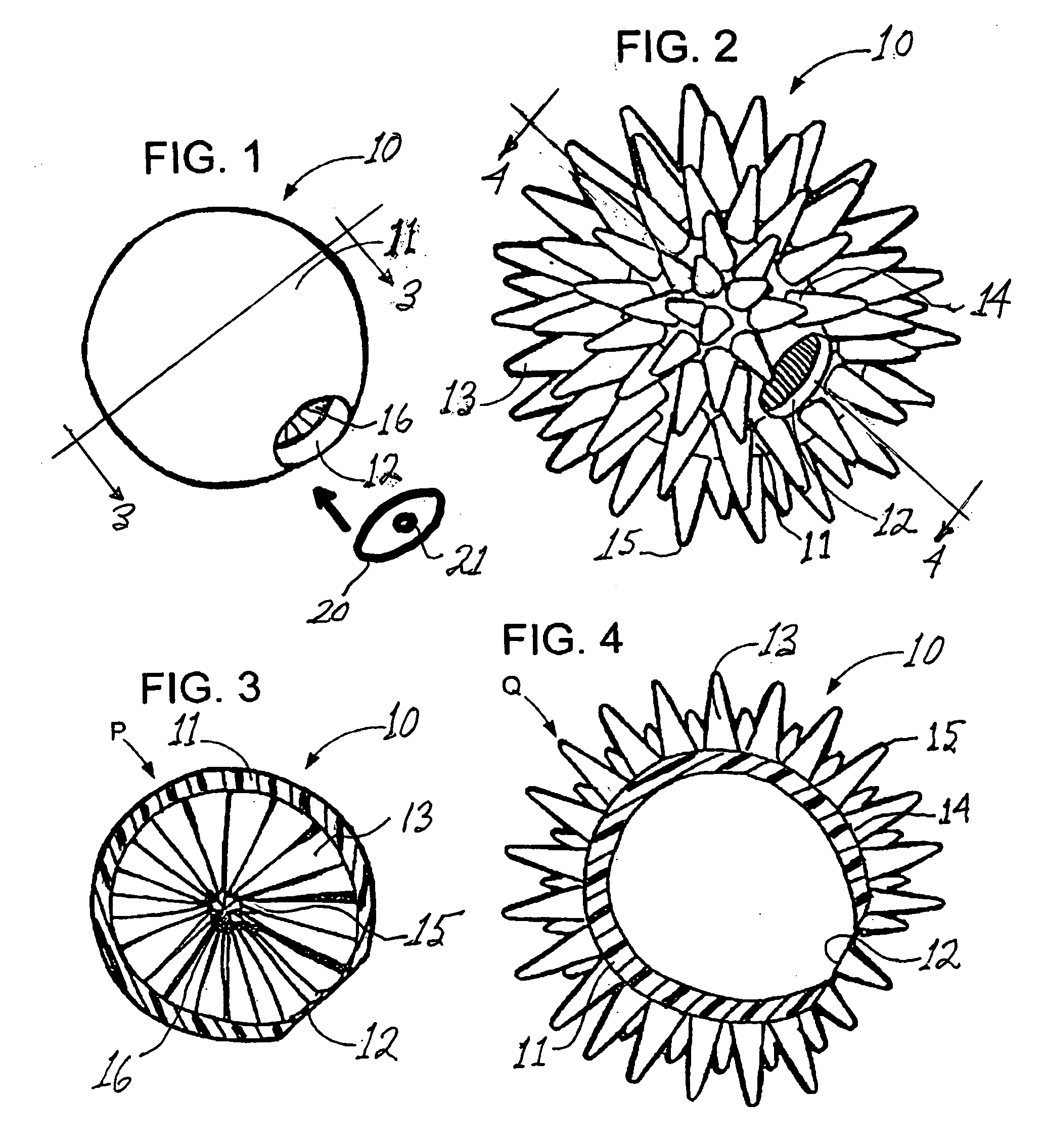
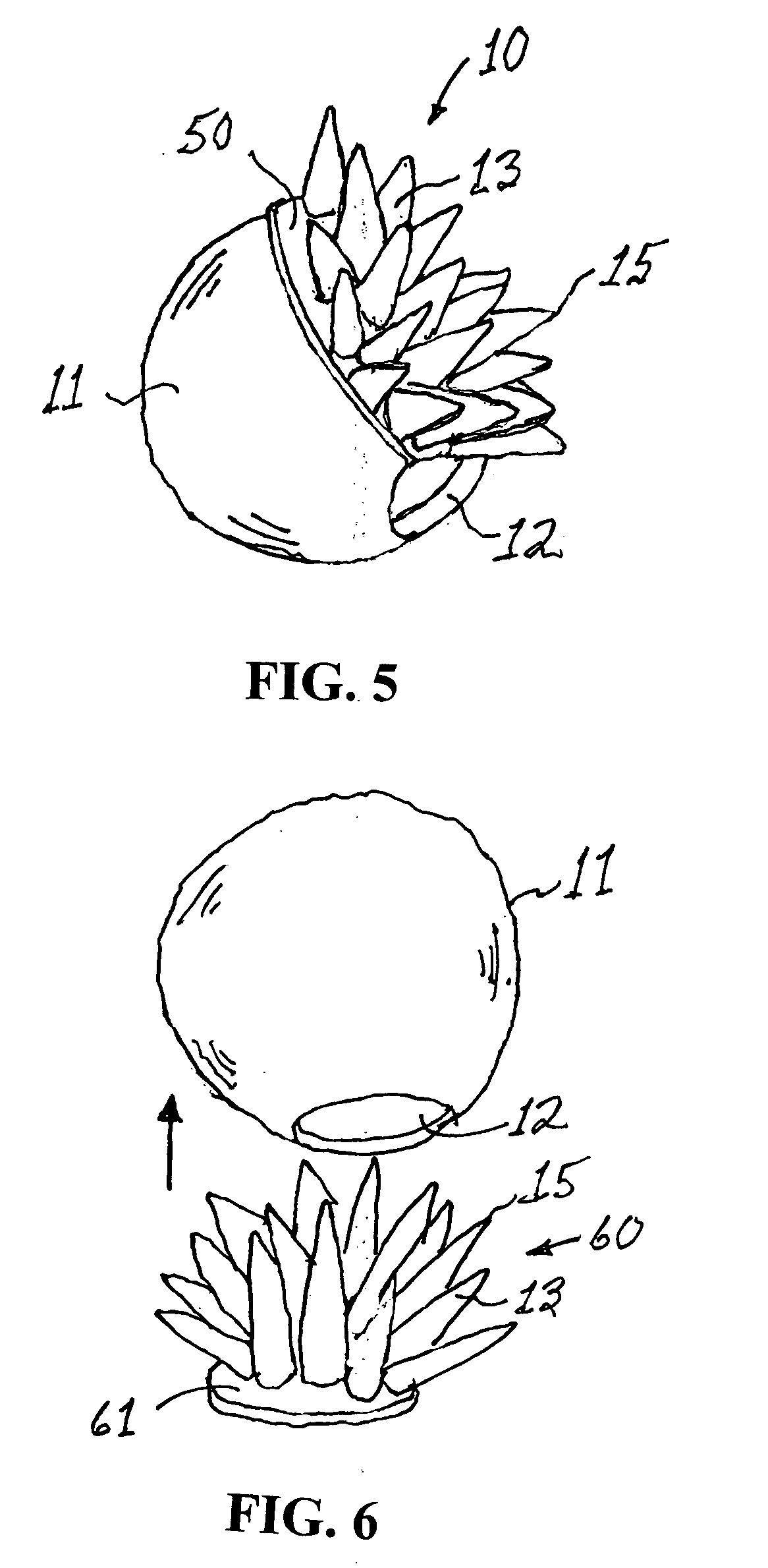
[0022] In FIG. 1 of the accompanying drawings there is schematically depicted an implantable breast prosthesis 10 in accordance with the present invention. Breast prosthesis 10 is preferably of unitary construction and is preferably formed in an everted configuration as shown in FIG. 2, by injecting a fluidic elastomer into a mold and curing the elastomer. The mold is separated, the (everted) breast prosthesis (FIG. 2) removed from the mold, then everted to provide the breast prosthesis 10 of FIG. 1. The inner surface of the shell 11 has a plurality of flexible elastomeric protruberances 13, preferably conical in shape, projecting radially inwardly from the surface of the shell and substantially filling the inner chamber of the prosthesis when the prosthesis is in the configuration shown in perspective view in FIG. 1 and cross-sectional view in FIG. 3. The term “flexible”, as used herein to describe a protruberance, means that the protruberance is elastically deformable.

[0023] Typi...


PUM


Abstract

A breast prosthesis has a flexible shell surrounding an interior compartment. An inner surface of the shell has a plurality of flexible protuberances or struts integral therewith that extend inwardly into the interior compartment. The opposing outer surface of the shell of the breast prosthesis is preferably textured to promote tissue ingrowth. A hole in the flexible shell allows the breast prosthesis to be made in an everted configuration, then everted to provide the prosthesis. In a preferred embodiment, the prosthesis does not contain a fluid filler material and is leak and rupture-proof. The breast prosthesis may be encased in a biocompatible elastomeric shell for implantation or be made from a suitable and inexpensive elastomer and worn as an explant. The prosthesis can be made in a variety of shapes for other types of soft tissue implants.

Description

[0001] This application claims the benefit of U.S. Provisional Application Ser. No. 60 / 668,558, filed Apr. 4, 2005.BACKGROUND OF THE INVENTION [0002] 1. Field of the Invention [0003] The present invention relates to a prosthesis for either implantation beneath the skin of a person or worn externally, and more particularly, to an implantable breast prosthesis. [0004] 2. Prior Art [0005] Surgical reconstruction of human breasts as a result of injury or as a result of partial or total mastectomy has been performed for many years. Various surgical prostheses have been developed for implantation in the human breast as a part of breast reconstruction or augmentation. Two major problems with prostheses heretofore used is rupture and the lack of maintained projection, particularly in a manner such that the proper shape and location on the chest wall would be achieved and maintained, and the fact that their shape and consistency generally does not match the remaining breast. In an effort to ...

Claims


Application Information

Patent Timeline
IPC IPC(8): A61F2/12A61F2/02
CPCA61F2/12
Inventor TIAHRT, LEIF K.
Owner TIAHRT LEIF K
Learn More