Method for operating a pneumatic device for the metered delivery of a liquid and pneumatic device

a pneumatic device and liquid technology, applied in the direction of liquid dispensing, liquid/fluent solid measurement, opening closed containers, etc., can solve the problems of affecting the co-ordination with the writing movement of the writing nozzle, and the volume of liquid delivered is not determined volumetrically, so as to achieve the effect of improving the operation in accordance with the invention and increasing the accuracy of the pressure level to be set in the pressure tank

Active Publication Date: 2006-10-12
ESEC
View PDF20 Cites 7 Cited by
  • Summary
  • Abstract
  • Description
  • Claims
  • Application Information

AI Technical Summary

Benefits of technology

[0009] Operation in accordance with the invention can be improved by means of further, optional measures. First namely in that the pressure sensor measures the pressure level PB1,ist achieved after pressure build-up and that the pressure pT2 prevailing in the pressure tank before the start of the next pressure pulse is adjusted so that the next time (or in the statistical average) the pressure level pB achieves the predetermined set value pB1. A change in the pressure level pB1,ist as a result of emptying the liquid container is therefore prevented. A second measure that comes to use as an alternative to the first measure, consists in measuring the progression of the pressure in the liquid container (or at the output of the pneumatic device) during the pressure pulse, calculating the time integral of the pressure and then adjusting the pressure pT2 to be achieved in the pressure tank before the start of the next pressure pulse so that the time integral of the pressure remains constant in the statistical average. With a pneumatic device with which the pressure prevailing in the pressure tank is not regulated but set, a third measure exists in that each time after conclusion of the pressure pulse, a higher pressure than the desired pressure is first produced in the pressure tank and then the pressure is reduced to the desired value. In this way, the accuracy of the pressure level to be set in the pressure tank can be increased especially with a comparatively low pressure level.

Problems solved by technology

However, it has the disadvantage that the amount of liquid delivered is not determined volumetrically as is the case for example with the mechanical pump described in the European patent application EP 979028.
These devices have two significant disadvantages: The amount of liquid delivered is dependent on the degree of emptying of the syringe.
This hampers the co-ordination with the writing movement of the writing nozzle.

Method used


Image

  • Method for operating a pneumatic device for the metered delivery of a liquid and pneumatic device
  • Method for operating a pneumatic device for the metered delivery of a liquid and pneumatic device
  • Method for operating a pneumatic device for the metered delivery of a liquid and pneumatic device

Examples


Embodiment Construction

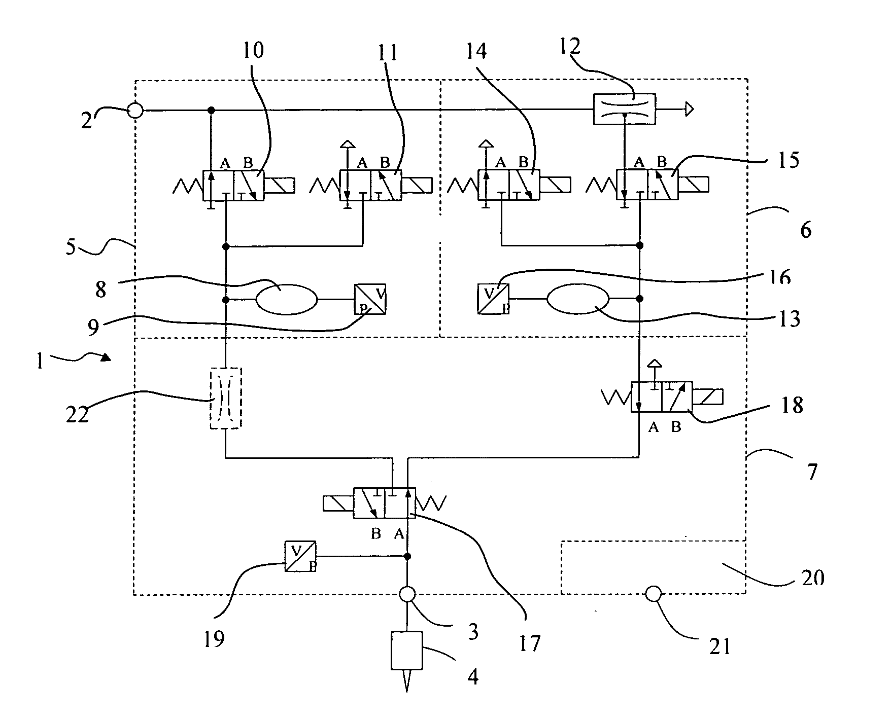
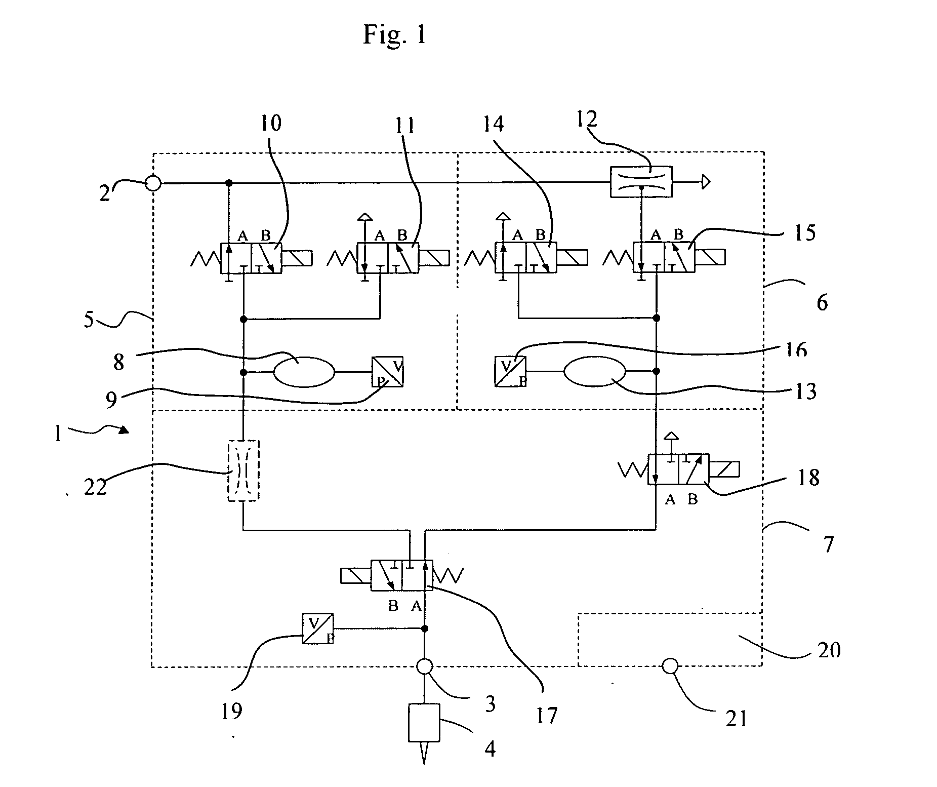
[0022]FIG. 1 shows a schematic view of a pneumatic device in accordance with the invention 1 for the metered delivery of a liquid that is particularly suited for carrying out the method in accordance with the invention explained above. The device 1 includes an input 2 for the supply of compressed air that is produced by an external compressed air source, and an output 3 that is connected to the liquid container 4 via a tube. The device 1 consists of three pneumatic sub-groups 5-7 that fulfil three sub-functions. The first sub-group 5 produces the upper pressure level that is required for delivery of the liquid. The second sub-group 6 produces the holding vacuum that is to prevent the liquid from dripping. The third sub-group 7 controls delivery of the liquid.

[0023] The first sub-group 5 comprises a pressure tank 8, a first pressure sensor 9 for measuring the pressure pT prevailing in the pressure tank 8, an inlet valve 10 for building up the pressure and an outlet valve 11 for redu...


PUM


Abstract

The invention concerns the operation of a pneumatic device for the metered delivery of a liquid and a pneumatic device particularly suited for operation in accordance with the invention. The pneumatic device has a pressure tank that can be connected to a compressed air source by means of an inlet valve and with the surroundings by means of an outlet valve. For delivery of the liquid, a pressure pulse is applied to the liquid container containing the liquid in that the pressure tank is temporarily connected to the liquid container via a changeover valve. After the end of the pressure pulse, the pressure prevailing in the pressure tank is increased to a value that is greater than the set value to be achieved during the pressure pulse.

Description

PRIORITY CLAIMS [0001] Applicant hereby claims foreign priority under 35 U.S.C § 119 from Swiss Application No. 654 / 05 filed Apr. 11, 2005, the disclosure of which is herein incorporated by reference. FIELD OF THE INVENTION [0002] The invention concerns a method for operating a pneumatic device for the metered delivery of a liquid as well as a pneumatic device that is used particularly when mounting semiconductor chips onto a substrate in order to apply a predetermined amount of adhesive to the substrate. BACKGROUND OF THE INVENTION [0003] Such a pneumatic device is suited for the metered delivery of viscous, sticky or chemically aggressive liquids. Compared with a mechanical pump, it has the advantage that it is subjected to little wear and can be more easily cleaned. However, it has the disadvantage that the amount of liquid delivered is not determined volumetrically as is the case for example with the mechanical pump described in the European patent application EP 979028. The ter...

Claims


Application Information

Patent Timeline
Patent Type & Authority Applications(United States)
IPC IPC(8): B67D5/54B67D7/06B67D7/72
CPCG01F13/00Y10T137/3127B67D1/12G01F11/00
Inventor KUCERA, LADISLAVVON ARX, MARTIN
Owner ESEC
Why Eureka
Try Eureka