Color image forming apparatus
a color image and forming apparatus technology, applied in the field of color image forming apparatus, can solve the problems of long image forming time, difficult to obtain a high-quality full-color image, high cost, etc., and achieve the effect of reducing color discrepancy, high-quality color image, and large increase in cos
- Summary
- Abstract
- Description
- Claims
- Application Information
AI Technical Summary
Benefits of technology
Problems solved by technology
Method used
Image
Examples
first embodiment
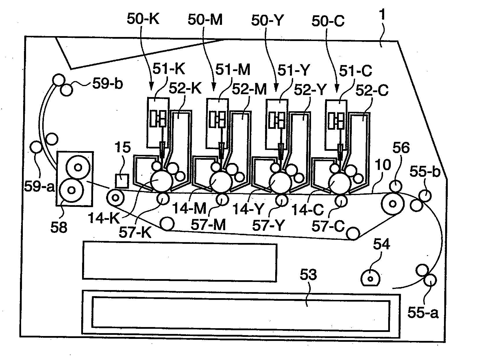
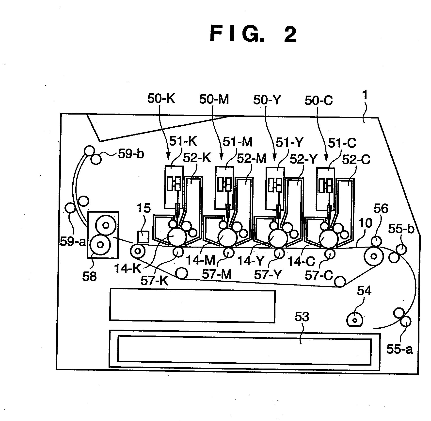
[0056]FIG. 2 is a schematic sectional view showing the arrangement of a color image forming apparatus according to this embodiment. A color image forming apparatus 1 shown in FIG. 2 is a color laser beam printer of a so-called tandem system, which comprises, e.g., four photosensitive drums. This color image forming apparatus 1 mounts a transfer material cassette 53 in a lower portion of the right side surface of its main body. Transfer materials set in the transfer material cassette 53 are picked up one by one by a paper feed roller 54, and each transfer material is fed to image forming units by guide roller pairs 55-a and 55-b. A feeding belt 10 that feeds the transfer material is stretched flat via a plurality of rotary rollers in the transfer material feeding direction (from the right to the left in FIG. 2), and the transfer material is electrostatically attracted on the most upstream portion of the feeding belt 10.
[0057] The color image forming apparatus 1 has four image formin...
second embodiment
[0133] In the second embodiment, when the density of the tone correction is switched at, e.g., three pixels in four levels, it is done at (a) a position where coordinate conversion is performed, (b) a position one pixel before the position where coordinate conversion is performed, and (c) a position two pixels before the position where coordinate conversion is performed.
[0134] Hence, the color discrepancy correction position arithmetic units 407C, 407M, 407Y, and 407K respectively calculate the position one pixel before the position where coordinate conversion is performed, and the position two pixels before the position where coordinate conversion is performed.
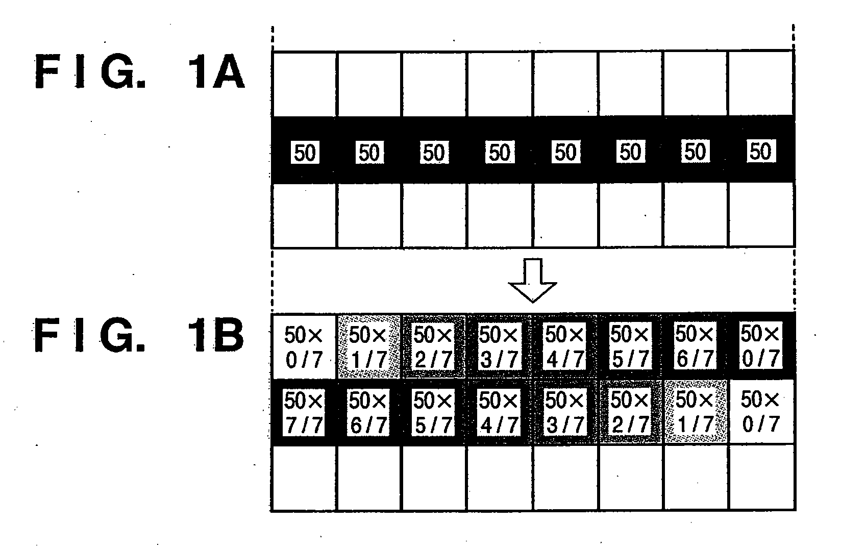
[0135]FIGS. 9A to 9G are views for explaining color discrepancy correction in less than the pixel unit by the tone corrector 804. The discrepancy amount correction in less than the pixel unit is implemented by adjusting the exposure ratios of neighboring dots in the sub-scan direction.
[0136]FIG. 9A shows an image of a main...
third embodiment
[0170] According to parent reference 2 (Japanese Patent Application Laid-Open No. 8-85237) described above, the output coordinate position of image data for each color is corrected for an image that has undergone halftone processing. For this reason, if dithering is applied, reproducibility of halftone dots of a halftone image deteriorates. As a result, color inconsistency may occur and moiré may become obvious. Furthermore, when such non-uniform density values are periodically repeated, moiré becomes obvious, and a high-quality color image cannot be obtained. The third embodiment solves such drawbacks.
[0171] A color image forming apparatus according to the embodiment of the present invention is also a four-drum color laser beam printer, and FIG. 2 will be quoted.
[0172]FIG. 10 is a conceptual view for explaining a misalignment of a main scan line scanned on each photosensitive drum 14 as an image carrier (for example, the photosensitive drum 14-C for cyan). Since the same applies ...
PUM
 Abstract
Description
Claims
Application Information
 - R&D
- Intellectual Property
- Life Sciences
- Materials
- Tech Scout
- Unparalleled Data Quality
- Higher Quality Content
- 60% Fewer Hallucinations
Browse by: Latest US Patents, China's latest patents, Technical Efficacy Thesaurus, Application Domain, Technology Topic, Popular Technical Reports.
© 2025 PatSnap. All rights reserved.Legal|Privacy policy|Modern Slavery Act Transparency Statement|Sitemap|About US| Contact US: help@patsnap.com


