
Integrated circuit device and method of producing the same

a technology of integrated circuits and circuits, applied in solid-state devices, basic electric elements, nanoinformatics, etc., can solve problems such as loss of reliability of lsi, approach reaching its limit, and breaking of wiring lines, so as to improve reliability and good resistance to migration

Inactive Publication Date: 2006-10-12
FUJITSU LTD
View PDF11 Cites 36 Cited by
  • Summary
  • Abstract
  • Description
  • Claims
  • Application Information

AI Technical Summary

Benefits of technology

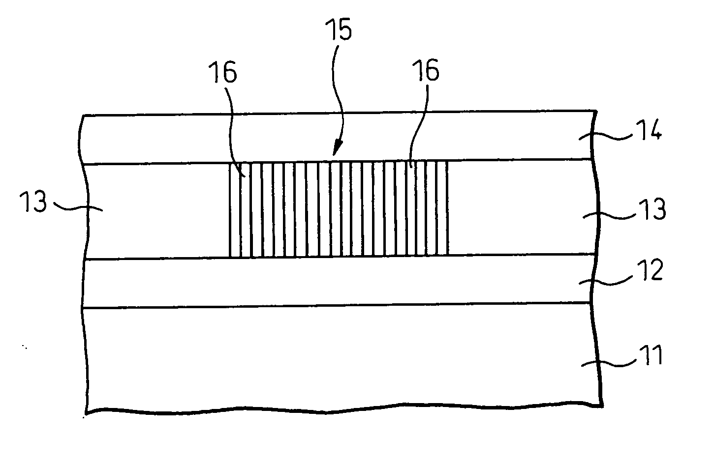
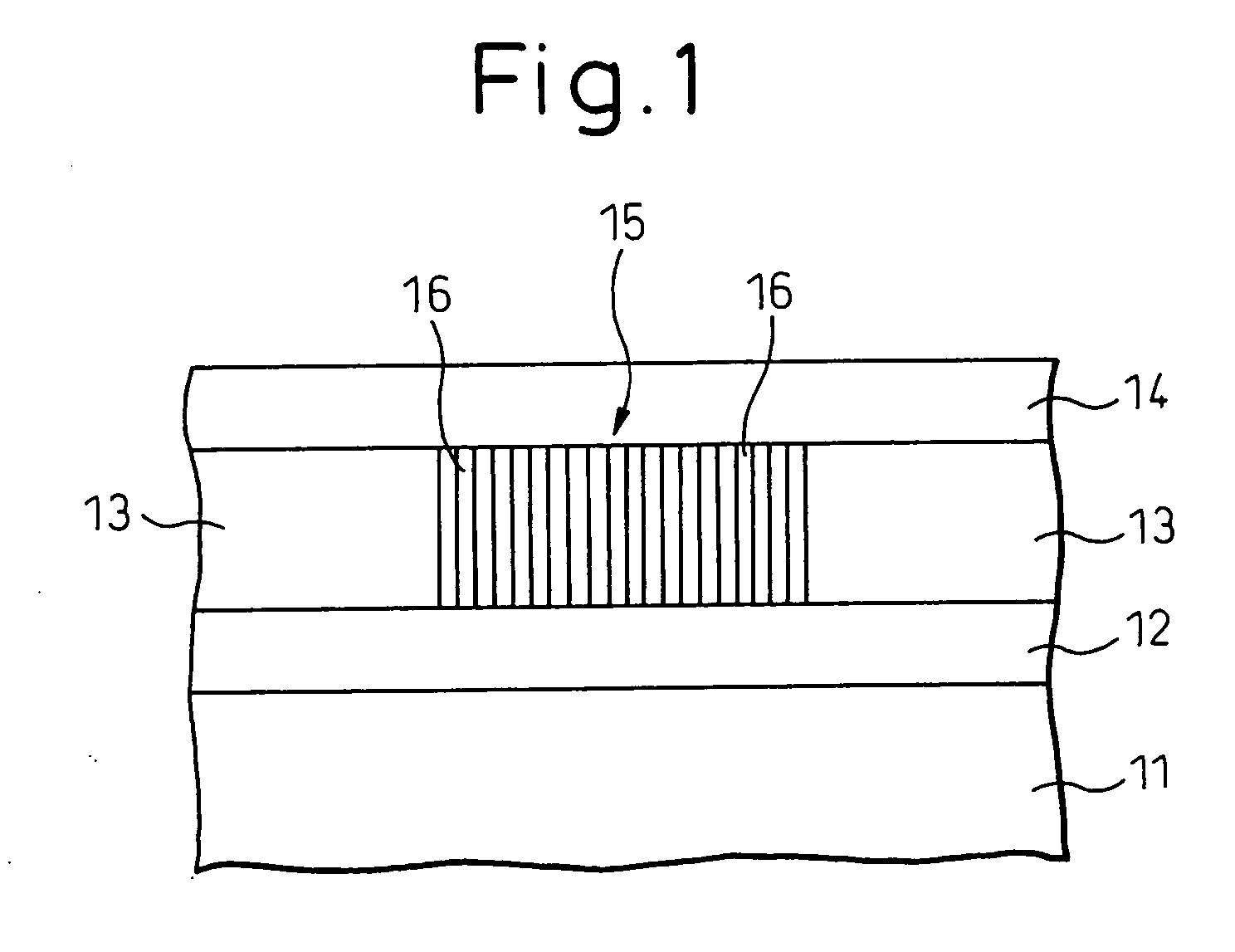
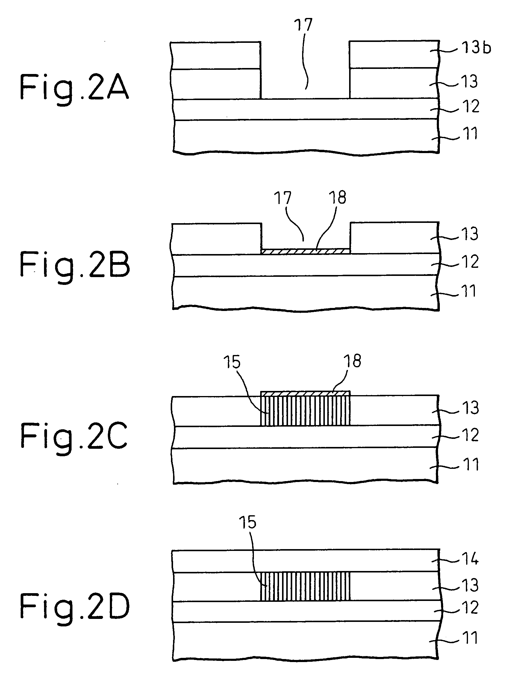
[0017] An object of the invention is to provide an integrated circuit device provided with vias having good resistance to migration causing the breaking of a wiring line, and having improved reliability.
[0019] Still another object of the invention is to provide a semiconductor device of quite novel type, and in particular to a semiconductor device in which the short channel effect can be effectively suppressed, while making possible the high-speed and the high-frequency operation with a high current driving ability.

Problems solved by technology

With a current LSI, a phenomenon of movement of a metal atom of a wiring material, which is known as a migration phenomenon, is noted as a factor in loss of reliability of the LSI.
This phenomenon can result in the breaking of a wiring line caused by stresses on the wiring metal material or electrons passing through the wiring line, and, in most cases, occurs particularly at a via for interconnecting wiring lines which must take a complex structure.
This approach would reach its limit sooner or later due to factors such as a limit of lithography technique.
The gate length has already been reduced to the order of 10 nm, which has posed many problems including the deteriorated matching accuracy due to fluctuations in lithography, an increased turn-off current of the transistor (short channel effect), a turn-on current saturation and an increased gate leakage current.
Nevertheless, the surround gate structure requires a cylindrical semiconductor layer extending upward of the substrate surface, which cannot be easily fabricated.
For example, the threshold voltage (the gate voltage for turning off the current flowing in the transistor) is liable to vary from one transistor to another, and the control of impurities concentration by doping is difficult.
The various problems including the aforementioned ones are inherent to the conventional field effect transistors, or especially, those extremely micronized, and are a stumbling block to the development of a field effect transistor having superior characteristics which have yet to be realized.
In the conventional organic polymer resist, however, a pattern of the order of 10 nm, which is smaller than the polymer molecule, cannot be resolved.
Also, insufficient resistance of the resist to dry etching makes it necessary to transfer the pattern to another film for etching.
Since the resolution of the resist has almost reached a limit, however, the gate formed by this method has large gate size fluctuations and inferior linearity.
This gate, therefore, is not suitable for practical applications.

Method used


Image

  • Integrated circuit device and method of producing the same
  • Integrated circuit device and method of producing the same
  • Integrated circuit device and method of producing the same

Examples


Embodiment Construction

[0071] In the invention, a cylindrical structure made up of carbon atoms, which is a nano-structure based on self-organizing, is used as a material for wiring lines or vias in an integrated circuit device. Such nano-structures include a nano-structure generally known as a carbon nanotube.

[0072] Carbon nanotube is a new carbon-based material, to which attention has recently been paid because of its unique properties. Carbon nanotube has a structure of a cylindrically rolled graphite sheet in which carbon atoms are arranged in the form of united six-membered rings through the strongest bond of sp2, the end of the tube being closed by several six-membered rings accompanied with five-membered rings. Carbon nanotube can have a fined diameter of down to the order of sub-nanometer, with the minimum diameter being 0.4 nanometer. The physical properties of this material are only now being studied, and it is known that the material has a coefficient of thermal conductivity greater than that ...


PUM


Abstract

An integrated circuit device having vias having good resistance to migration causing the breaking of a wiring line, or an integrated circuit device having a wiring structure that is fined by breaking the limit of lithography technique is provided. The former device comprises a plurality of elements fabricated on a semiconductor substrate, wiring lines for making the elements and the integrated circuit device function, and vias for interconnecting wiring lines in separate layers, the via being formed of one or more cylindrical structures made up of carbon atoms. The latter device comprises a plurality of elements fabricated on a semiconductor substrate and wiring members for making the elements and the integrated circuit device function, at least part of the wiring members being formed of one or more cylindrical structures made up of carbon atoms. The latter device is preferably manufactured by a method comprising using a CVD process for the formation of the cylindrical structures, while applying a direct current electric field so as to grow the cylindrical structures in one direction, or applying an alternating current electric field so as to grow the cylindrical structures in two directions. A semiconductor device using a carbon nanotube and a method of forming a pattern using a carbon nanotube as a mask are also disclosed.

Description

BACKGROUND OF THE INVENTION [0001] 1. Field of the Invention [0002] The invention relates to an integrated circuit device and, more particularly, to an integrated circuit device in which a cylindrical structure made up of carbon atoms is used as a material for a wiring member or a material for a via interconnecting wiring lines located in separate layers. [0003] Also, the present invention relates to a semiconductor device, and in particular to a semiconductor device of a new type made up of a cylindrical multilayer structure or, typically, a new material called carbon nanotube. [0004] Further, the present invention relates to a transistor, and in particular to a field effect transistor made of carbon nanotubes having metallic characteristics used as a gate material. [0005] Furthermore, the present invention relates to a method of forming a micro pattern using carbon nanotubes as a masking material for dry etching. [0006] 2. Description of the Related Art [0007] A half of a century ...

Claims


Application Information

Patent Timeline
Patent Type & Authority Applications(United States)
IPC IPC(8): H01L23/48H01L23/52H01L29/40H01L21/285H01L21/335H01L21/768H01L23/532H01L29/778H01L51/30
CPCB82Y10/00H01L21/28562H01L2924/0002H01L21/28581H01L21/76838H01L21/76879H01L23/53276H01L29/42316H01L29/475H01L29/66431H01L29/66454H01L29/7783H01L29/7784H01L51/0048H01L2221/1094Y10S977/742Y10S977/762Y10S977/765Y10S977/766H01L2924/00H10K85/221
Inventor AWANO, YUJI
Owner FUJITSU LTD
Learn More