Apparatus for delivering a tool into a submerged bore

a technology of submerged bores and apparatus, which is applied in the direction of well accessories, borehole/well accessories, nuclear elements, etc., can solve the problems of difficult positioning, difficult manual manipulation of these poles and funnels, and the likely only partial inspection of inspections, so as to reduce the outage time of nuclear reactors and reduce costs

Inactive Publication Date: 2006-10-12
GENERAL ELECTRIC CO
View PDF35 Cites 28 Cited by
  • Summary
  • Abstract
  • Description
  • Claims
  • Application Information

AI Technical Summary

Benefits of technology

[0009] The inventors hereof have succeeded at designing an apparatus that is remotely positionable for delivering, inserting, and operating a tool within a submerged bore. This includes a system that can be placed into a reactor pool with minimal and possibly no refuel bridge support. Also, the system can provide for remotely positioning, inserting, and operating an inspection tool within a jet pump of a nuclear reactor. The various embodiments of the invention provide for a system for inspecting submerged bores such as nuclear reactor jet pumps that can provide for minimal or no use of the refuel bridge and fewer operating personnel to perform the tool delivery, and inspecting process. As such, the system can provide decreased costs associated with inspecting jet pumps or other submerged bores and reduced outage time of a nuclear reactor.

Problems solved by technology

While examinations in the annulus or region between a shroud and a pressure vessel wall can be performed, these examinations are likely to be only partial inspections due to access limitations in the annular region of the reactor.
As the inlet to the jet pumps are submerged, often up to 50 feet under the surface of the pool, the manual manipulation of these poles and the funnel is difficult and time consuming.
However, such systems are difficult to position and require considerable operator involvement and still require manual placement on each jet pump.
Additionally, as they require use of the full bridge, they require coordination with refueling operations and often result in additional reactor outage time.
These processes often require more than one operator.
As such, current systems and methods for inspecting the inside of a submerged bore such as a nuclear reactor jet pump that can be submerged 50 feet below the surface of a water pool are difficult, time consuming, and costly.

Method used


Image

  • Apparatus for delivering a tool into a submerged bore
  • Apparatus for delivering a tool into a submerged bore
  • Apparatus for delivering a tool into a submerged bore

Examples


Embodiment Construction

[0020] The following description is merely exemplary in nature and is in no way intended to limit the invention, its applications, or uses.

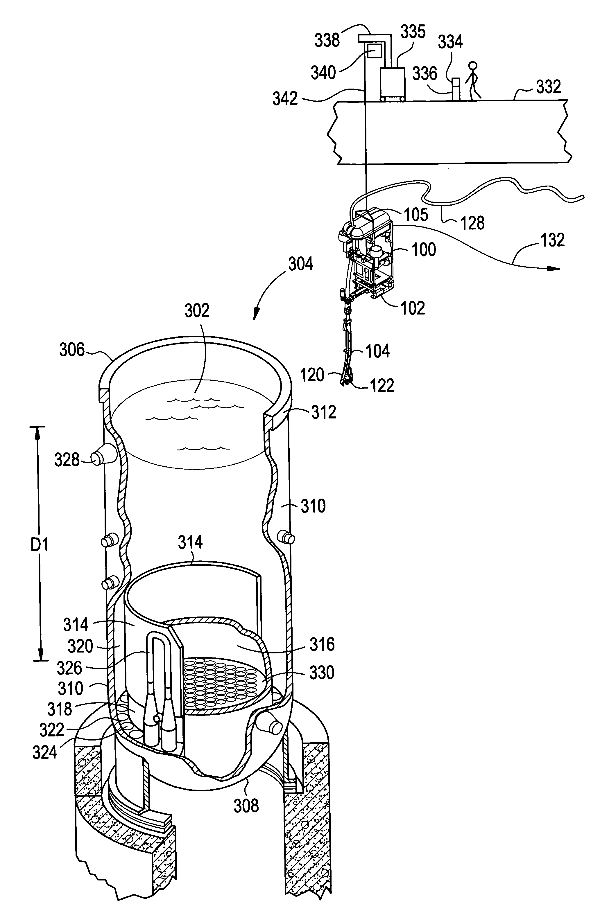
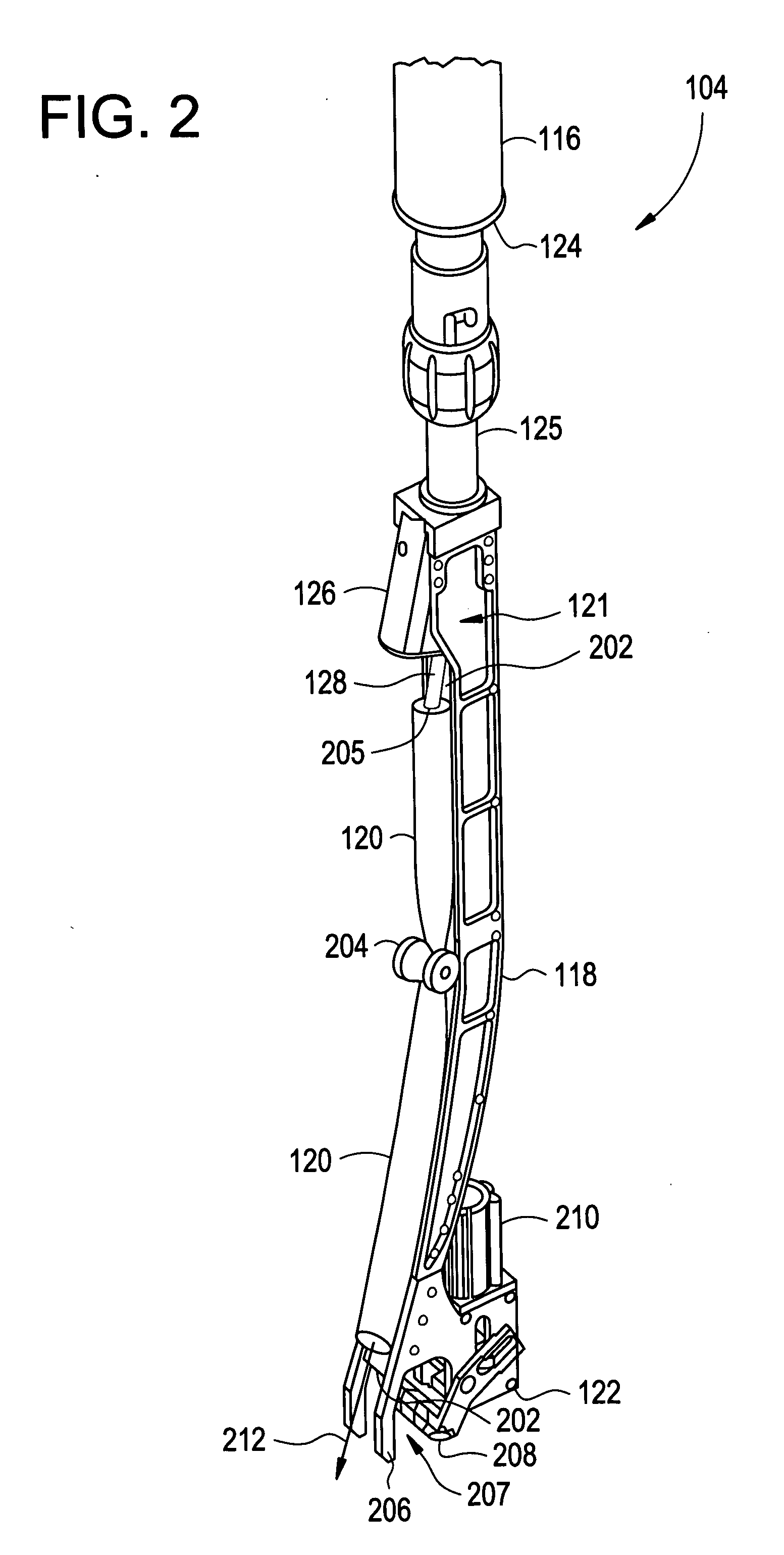
[0021] An inspection delivery assembly, according to various embodiments of the invention, includes a frame, and a propulsion unit for controlling the movement of the tool delivery apparatus within a pool of liquid. A guide assembly provides for delivery and insertion of the tool into an inlet of the jet pump and includes a bore insertion portion. A tool position driver provides for controlling the vertical position of the tool in relation to the guide assembly.

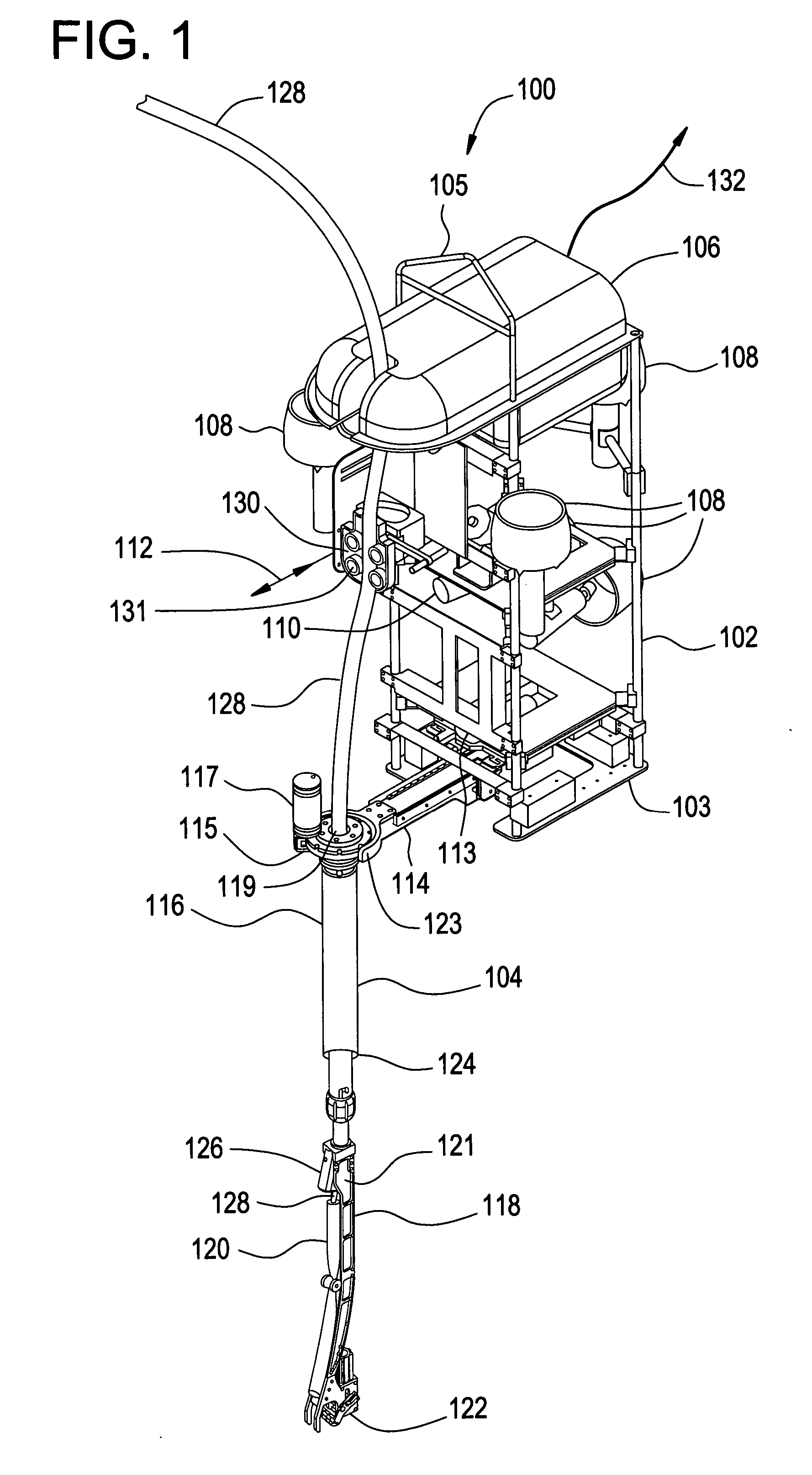
[0022] Referring to FIG. 1, one exemplary embodiment of an inspection tool delivery assembly 100 according to the invention is illustrated. In FIG. 1, the tool delivery assembly 100 includes a submarine assembly 102 and a guide assembly 104. The submarine assembly 102 includes a structural frame 103 for supporting the various components of the submarine assembly 102 and can take any form...


PUM


Abstract

An apparatus for delivering a tool into a nuclear reactor jet pump submerged in a reactor pool includes a frame, and a propulsion unit for controlling the movement of the tool delivery apparatus within a pool of liquid. A guide assembly provides for delivery and insertion of the tool into an inlet of the jet pump and includes a bore insertion portion. A tool position driver provides for controlling the vertical position of the tool in relation to the guide assembly.

Description

CROSS-REFERENCE TO RELATED APPLICATIONS [0001] This application is related to U.S. application Ser. No. ______, attorney docket no. 162006-1 filed on Apr. 12, 2005, coincidental with the filing of the present application.FIELD OF THE INVENTION [0002] This invention relates generally to an apparatus for delivering a tool to a submerged bore, and more particularly to a assembly for delivering an inspection tool into a submerged nuclear reactor jet pump. BACKGROUND OF THE INVENTION [0003] Bores such as pipes or cylindrically shaped equipment are often submerged in a pool of water or other liquid. There is often a need to have a maintenance tool or inspection probe delivered into the submerged bore. For example, a reactor pressure vessel (RPV) of a boiling water reactor (BWR) typically has submerged bores that need to be inspected during maintenance routines. Hollow tubular jet pumps having internal bores are positioned within an annulus to provide the required reactor core water flow. ...

Claims


Application Information

Patent Timeline
Patent Type & Authority Applications(United States)
IPC IPC(8): E21B31/00
CPCF04F5/464G21C17/003G21Y2002/202G21Y2004/504G21Y2002/401G21Y2004/401G21Y2004/501G21Y2002/205Y02E30/30
Inventor SMITH, JARREDMATSUMOTO, JACK TOSHIOWELSH, CHRISTOPHER MARTINDAVIS, TREVOR JAMESGRINNELL, JEFFREY JOHNKETCHAN, DAVID PLATT
Owner GENERAL ELECTRIC CO
Why Eureka
Try Eureka