System and Method for Automatically Mounting a Pellicle Assembly on a Photomask

Inactive Publication Date: 2006-10-12
TOPPAN PHOTOMASKS INC
View PDF3 Cites 5 Cited by
  • Summary
  • Abstract
  • Description
  • Claims
  • Application Information

AI Technical Summary

Benefits of technology

[0012] Important technical advantages of certain embodiments of the present invention include a pellicle mounting technique that reduces or eliminates adhesion errors during a mounting process. During the mounting process, load cells located in a back plate of a mounting apparatus measure the force being applied to a photomask and a pellicle assembly by the mounting apparatus. If the applied force is greater than a minimum force, the load cells communicate electrical signals to a controller associated with the mounting apparatus. If the controller receives the electrical signals, the mounting process is completed and a conforming photomask assembly is generated. If the controller does not receive the electrical signals, the controller determines that a non-conforming photomask assembly has been formed and the controller prevents the non-conforming p

Problems solved by technology

As feature sizes of semiconductor devices decrease, the corresponding circuit images on the photomask also become smaller and more complex.
Due to the opaque nature of the absorber layer, inspecting and controlling the adhesion of the pellicle to the photomask is a difficult task.
However, excursions from the normal protocol may not be detected, which can lead to contamination under the pellicle, damage to the membrane, or even damage to the photomask itself.
Current industry standard pellicle application tools do not allow the measurement of the force distribution, making controlling, or even understanding the effect of, this force an impossibility.
However

Method used


Image

  • System and Method for Automatically Mounting a Pellicle Assembly on a Photomask
  • System and Method for Automatically Mounting a Pellicle Assembly on a Photomask
  • System and Method for Automatically Mounting a Pellicle Assembly on a Photomask

Examples


Example

[0024] Preferred embodiments of the present invention and their advantages are best understood by reference to FIGS. 1 through 5, where like numbers are used to indicate like and corresponding parts.

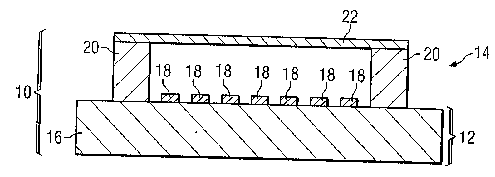
[0025]FIG. 1 illustrates a cross-sectional view of photomask assembly 10 assembled in a pellicle mounting system. Photomask assembly 10 includes pellicle assembly 14 mounted on photomask 12 by the pellicle mounting system. Substrate 16 and patterned layer 18 form photomask 12, otherwise known as a mask or reticle, that may have a variety of sizes and shapes, including but not limited to round, rectangular, or square. Photomask 12 may also be any variety of photomask types, including, but not limited to, a one-time master, a five-inch reticle, a six-inch reticle, a nine-inch reticle or any other appropriately sized reticle that may be used to project an image of a circuit pattern onto a semiconductor wafer. Photomask 12 may further be a binary mask, a phase shift mask (PSM), an optical p...


PUM


Abstract

A system and method for automatically mounting a pellicle assembly on a photomask are disclosed. The method includes loading a photomask into a mounting apparatus and loading a pellicle assembly into a back plate of the mounting apparatus opposite the photomask. The back plate includes at least one load cell that measures a force applied by the mounting apparatus to the photomask and the pellicle assembly. The measured force associated with the at least one load cell is received and the pellicle assembly is mounted on the photomask to create a photomask assembly if the measured force is greater than or approximately equal to a minimum force.

Description

RELATED APPLICATION [0001] This application is a Continuation of International Patent Application No. US / 04 / 032890 filed Oct. 5, 2004, which designates the United States and claims the benefit of U.S. Provisional Patent Application Ser. No. 60 / 509,087 entitled “SYSTEM AND METHOD FOR AUTOMATICALLY MOUNTING A PELLICLE ASSEMBLY ON A PHOTOMASK” filed by Ethan M. Frye et al. on Oct. 6, 2003.TECHNICAL FIELD OF THE INVENTION [0002] The present invention relates in general to photomask manufacturing and, more particularly to a system and method for automatically mounting a pellicle assembly on a photomask. BACKGROUND OF THE INVENTION [0003] As semiconductor device manufacturers continue to produce smaller devices, the requirements for photomasks used in the fabrication of these devices continue to tighten. Photomasks, also known as reticles or masks, typically consist of substrates that have an absorber layer formed on the substrate. The absorber layer includes a pattern representing a circ...

Claims


Application Information

Patent Timeline
IPC IPC(8): G03B27/62G03F1/64H01L
CPCG03F7/70983G03F1/64
Inventor FRYE, ETHAN M.GRIFFIN, KEVIN L.WILES, BART A.HENDRICKSON, PETER A.SHEPLER, JENNIFER M.
Owner TOPPAN PHOTOMASKS INC
Why Eureka
Try Eureka