Magnetic disk storage apparatus

a magnetic disk and storage device technology, applied in the direction of electronic commutators, record information storage, instruments, etc., can solve the problems of increasing hardware, unable to smoothly perform phase switching of output currents in response to an increase or decrease in output currents, and achieve high-accuracy rotation control. , the effect of simplifying circuit configuration and arithmetic programs

Inactive Publication Date: 2006-10-12
RENESAS TECH CORP +1
View PDF9 Cites 1 Cited by
  • Summary
  • Abstract
  • Description
  • Claims
  • Application Information

AI Technical Summary

Benefits of technology

[0005] An object of the present invention is to provide a magnetic disk unit that can feed currents of sine waveforms through coils by a relatively small-sized circuit, and thereby, enables highly dense magnetic storage with less rotation variations and has a spindle motor rotating at a low noise level.
[0017] Moreover, in a magnetic disk storage apparatus comprising the first motor driving control circuit and a controller controlling the first motor driving control circuit, the first motor driving control circuit is constructed to perform control so that the total of currents fed through the coils of the phases matches a current indication value supplied from the controller, and a current indication value correcting circuit is provided which corrects the current indication value, taking into account fluctuations of the total current produced by the currents fed through the coils of the phases being changed according to sine waveforms. Accordingly, reaction of the control system to ripples of coil current resulting from driving the motor with a sine waveform can be weakened, with the result that torque ripples can be reduced and rotation variations can be further lessened.

Problems solved by technology

As a result, the amount of hardware increases, and even if the load on the motor changes, since the duty of basic clock to form coil drive waveforms remains constant, phase switching of output currents cannot be smoothly performed in response to an increase or decrease in the output currents.

Method used


Image

  • Magnetic disk storage apparatus
  • Magnetic disk storage apparatus
  • Magnetic disk storage apparatus

Examples


second embodiment

[0079]FIG. 12 shows a configuration of major parts of a motor driving control circuit in the present invention.

first embodiment

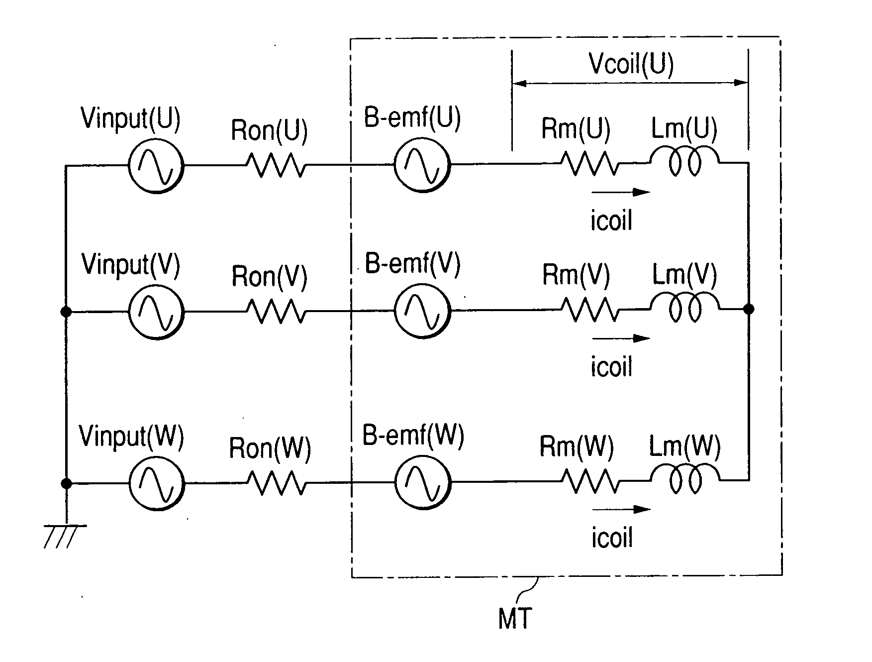
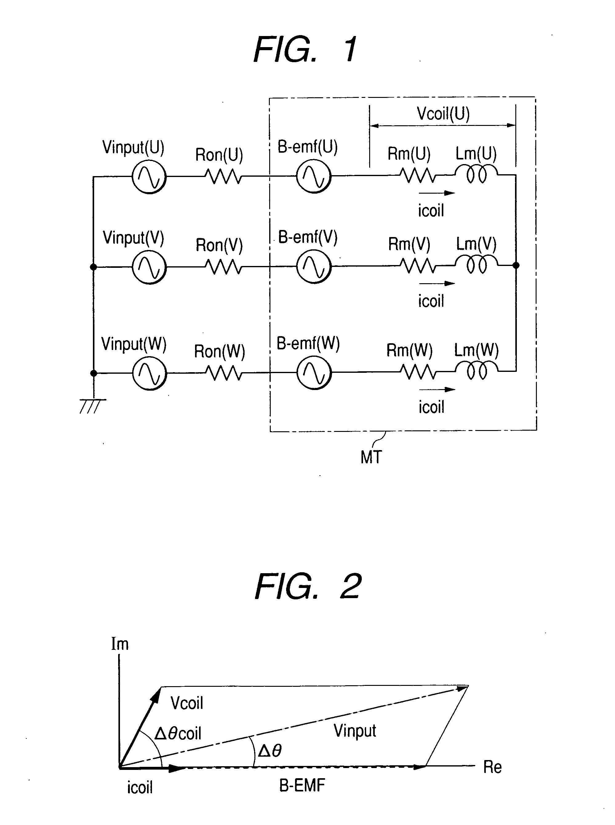
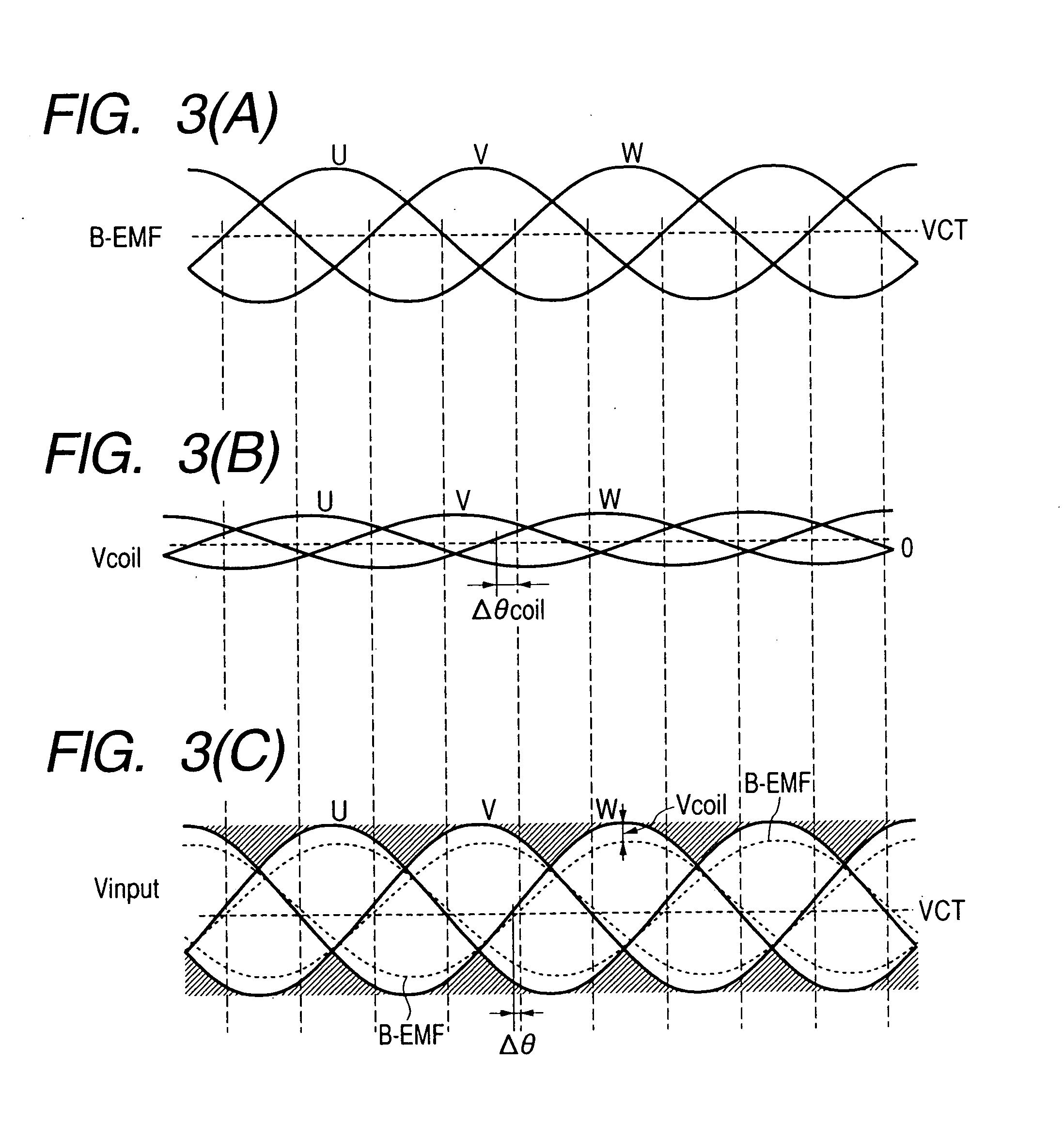
[0080] As described previously, the motor driving control circuit of the first embodiment is provided with the current detection resistor RNF for detecting a total current flowing through the three coils Lu, Lv, and Lw and the differential amplifier 13, wherein a difference between a detected coil current value and a current indication value supplied from the controller (CPU) outside the drawing is detected, and a PWM signal is produced to drive the output transistor so as to make the difference zero so that output current fed through the coils is subjected to feedback control. On the other hand, in the motor driving control circuit of the present embodiment, since coils of three phases of the motor are driven with three sine waveforms that are 120 degrees out of phase with one another, a total current Itotal flowing through the motor fluctuates and forms a rippled waveform indicated by a solid line B in FIG. 13.

[0081] If the total current is detected by the current detection resist...


PUM

PropertyMeasurementUnit
electrical angleaaaaaaaaaa
frequencyaaaaaaaaaa
frequenciesaaaaaaaaaa

Abstract

Currents of sine waveforms can be fed through coils by a relatively small-sized circuit, and thereby, highly dense magnetic storage can be realized with less rotation variations and a driving control circuit of a motor rotating at a low noise level can be provided. A coil of one phase of a three-phase brushless motor is driven with full amplitude at which an applied voltage becomes equal to a source voltage, and a coil of one of other phases is driven with gradually changing voltages so that a current of sine waveform is delivered, and a coil of the remaining phase is driven by feedback control so that a total current flowing through all coils becomes a predetermined current value.

Description

BACKGROUND OF THE INVENTION [0001] The present invention relates to technology for driving control of a brushless motor, and more particularly to technology effectively applied to the formation of rotation drive current waveforms of the motor. The present invention relates to technology effectively applied to a driving control apparatus of a spindle motor for rotationally driving disk type storage media as in, e.g., a hard disk drive. [0002] A hard disk drive is demanded to have the ability to read and write information from and to magnetic disk as fast as possible, that is, the ability to make access at high speed. To achieve this, it is important to speed up disk rotation. Conventionally, a brushless DC multi-phase motor called a spindle motor has been generally used to rotate magnetic disk in a hard disk drive. The magnetic disk is fast rotated by the spindle motor and a magnetic head for read and writing is brought near to the surface of the rotating magnetic disk to write or re...

Claims


Application Information

Patent Timeline
Patent Type & Authority Applications(United States)
IPC IPC(8): G11B15/46G11B19/20G11B19/247G11B19/28H02P6/06H02P6/08H02P6/18H02P6/182H02P6/28
CPCG11B19/247H02P6/08H02P6/002H02P6/28G11B19/20
Inventor KIMURA, REIICHIKOKAMI, YASUHIKOKAWAUCHI, KUNIHIROKUROSAWA, MINORUITAGAKI, KICHIYA
Owner RENESAS TECH CORP
Why Eureka
Try Eureka