Scalable spherical laser

a spherical laser and spherical resonant technology, applied in lasers, optical resonators, laser shapes and constructions, etc., can solve the problems of limiting the scalability and the maximum output power of conventional lasers, and achieve the effect of increasing both radii proportionally, scalable power source, and constant cavity length

Active Publication Date: 2006-10-12
RONALD LACOMB
View PDF7 Cites 13 Cited by
  • Summary
  • Abstract
  • Description
  • Claims
  • Application Information

AI Technical Summary

Benefits of technology

[0008] The optical cavity resonator supports spherical modes, e.g., radial and angular modes. The output power is scalable with spherical geometry. The radial components of the spherical modes depend upon the difference in radii between the inner and outer spheres. Increasing both radii proportionally while maintaining a constant cavity length (e.g., distance of separation between the spheres) increases the active cavity volume without affecting the nature of the radial modes and saturation conditions of the amplifying medium. This results in a scalable power source.

Problems solved by technology

Gain saturation and second order effects limit the maximum output power of conventional lasers, thereby limiting their scalability.

Method used


Image

  • Scalable spherical laser
  • Scalable spherical laser
  • Scalable spherical laser

Examples


Embodiment Construction

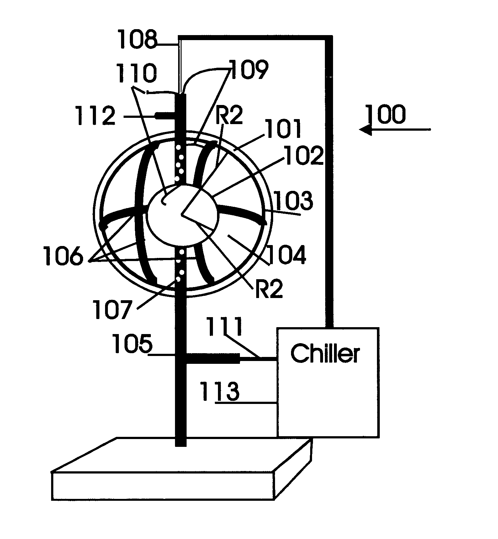
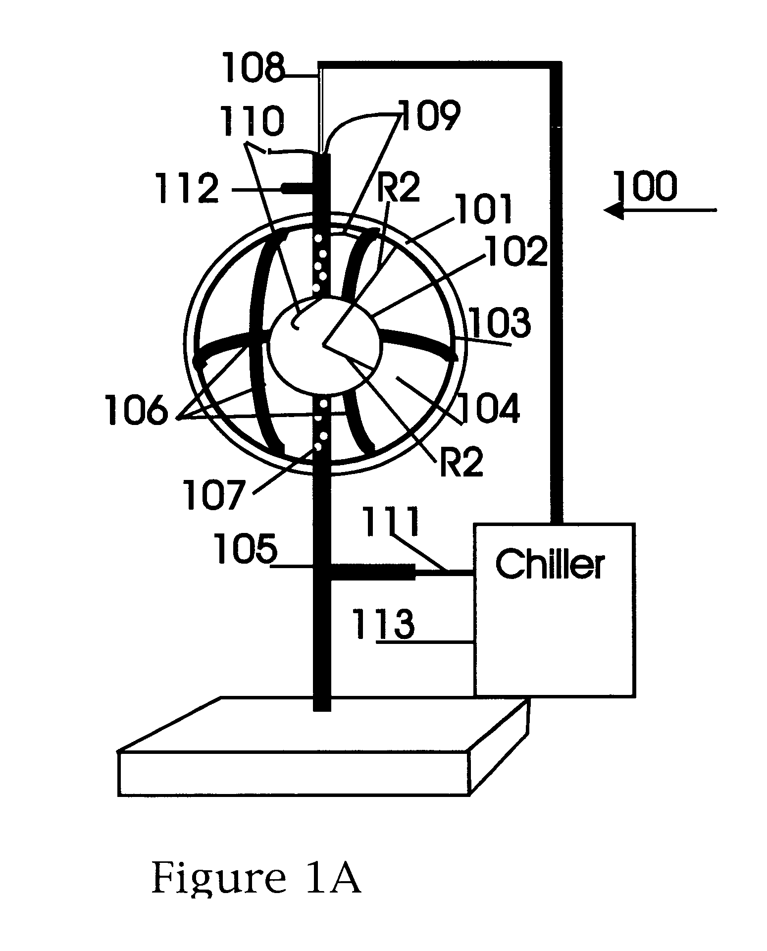
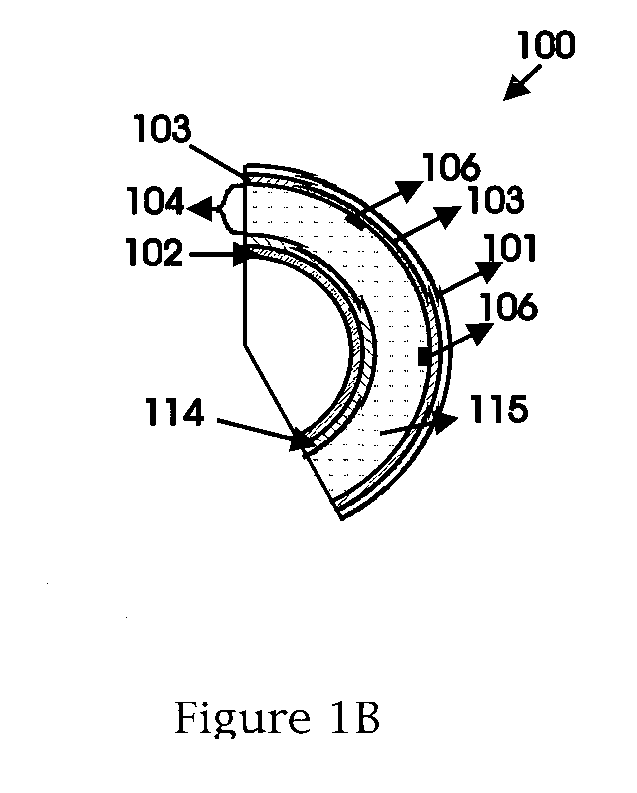
[0020] A first embodiment of a scalable spherical laser 100 is shown in FIGS. 1A and 1B. The laser 100 is applicable for use with active amplifying media that do not rely upon vessel sidewall collisions for population inversion. These include molecular, chemical, and similar active media. The spherical laser 100 includes an outer, hollow, vessel-like, generally spherical body 101 (“outer sphere”) and an inner, hollow, generally spherical vessel 102 (“inner sphere”). The inner and outer spheres may be concentric. The outer sphere 101 is occasionally referred to herein as the output coupler (“OC”) of the laser 100. The outer sphere 101 (shown in cross section in FIG. 1 to illustrate internal components) has a radius R1 greater than that of a radius R2 of the inner sphere 102, e.g., R1>R2. The spheres 101, 102 may be made of glass, quartz, metal, another suitable substrate material, or a combination thereof. A reflective coating is provided on at least one surface of each of the concen...


PUM


Abstract

A spherical laser includes a transparent or semi-transparent outer spherical vessel having an internal cavity, an amplifying medium in the cavity, and means to excite the amplifying medium. The sphere is provided with a partially reflective coating to act as a spherical optical resonator. Excitation of the amplifying medium produces an optical gain. When the gain exceeds cavity losses and threshold conditions are met, lasing is supported. This creates a three-dimensional, spherically radiating emission, emulating a point source. The output is radially diverging, but is harnessed by enclosing the sphere within a mirrored ellipse to image the output to a point, or within a mirrored parabola to columinate the emission. A concentric, reflective inner sphere may be disposed in the cavity, with the amplifying medium lying between the two spheres. A voltage potential is applied between the spheres to excite the medium.

Description

CROSS REFERENCE TO RELATED APPLICATIONS [0001] This application claims the benefit of U.S. Provisional Application Ser. No. 60 / 669,960, filed Apr. 11, 2005, U.S. Provisional Application Ser. No. 60 / 757,608, filed Jan. 11, 2006, and U.S. Provisional Application Ser. No. 60 / 763,772, filed Feb. 1, 2006, all of which are hereby incorporated by reference herein in their entireties.FIELD OF THE INVENTION [0002] The present invention relates to coherent light generators and, more particularly, to coherent light generations having a spherical resonant cavity. BACKGROUND OF THE INVENTION [0003] Modern lasers including semiconductor lasers, gas lasers, and solid state lasers utilize optical cavities consisting of two mirrors or prisms arranged to form closed optical paths of low loss, into which an amplifying medium is inserted. The amplifying medium enclosed within the optical cavity may be gaseous, liquid, crystalline, or a glassy solid. Laser oscillation will occur at specific frequencies ...

Claims


Application Information

Patent Timeline
Patent Type & Authority Applications(United States)
IPC IPC(8): H01S3/09
CPCH01S3/005H01S3/03H01S3/08H01S3/05H01S3/0602H01S3/0407
Inventor TOWNSEND, SALLIE S.LACOMB, RONALD
Owner RONALD LACOMB
Why Eureka
Try Eureka