Mode tailored spherical laser

a spherical laser and mode-tailored technology, applied in the direction of laser cooling arrangement, laser details, excitation process/apparatus, etc., can solve the problems of limiting the scalability and the maximum output power of conventional lasers, and achieve constant cavity length, scalable power source, and increase of both radii proportionally

Active Publication Date: 2013-12-05
LACOMB RONALD
View PDF2 Cites 7 Cited by
  • Summary
  • Abstract
  • Description
  • Claims
  • Application Information

AI Technical Summary

Benefits of technology

[0009]The optical cavity resonator supports spherical modes, e.g., radial and angular modes. The output power is scalable with spherical geometry. The radial components of the spherical modes depend upon the difference in radii between the inner and outer spheres. Increasing both radii

Problems solved by technology

Gain saturation and second order effects limit the maximum output

Method used


Image

  • Mode tailored spherical laser
  • Mode tailored spherical laser
  • Mode tailored spherical laser

Examples


Embodiment Construction

[0046]A Scalable Spherical Laser is described in U.S. Pat. No. 7,492,805, which list the present inventor Ronald LaComb and Sallie Townsend as inventors and is incorporated herein by reference.

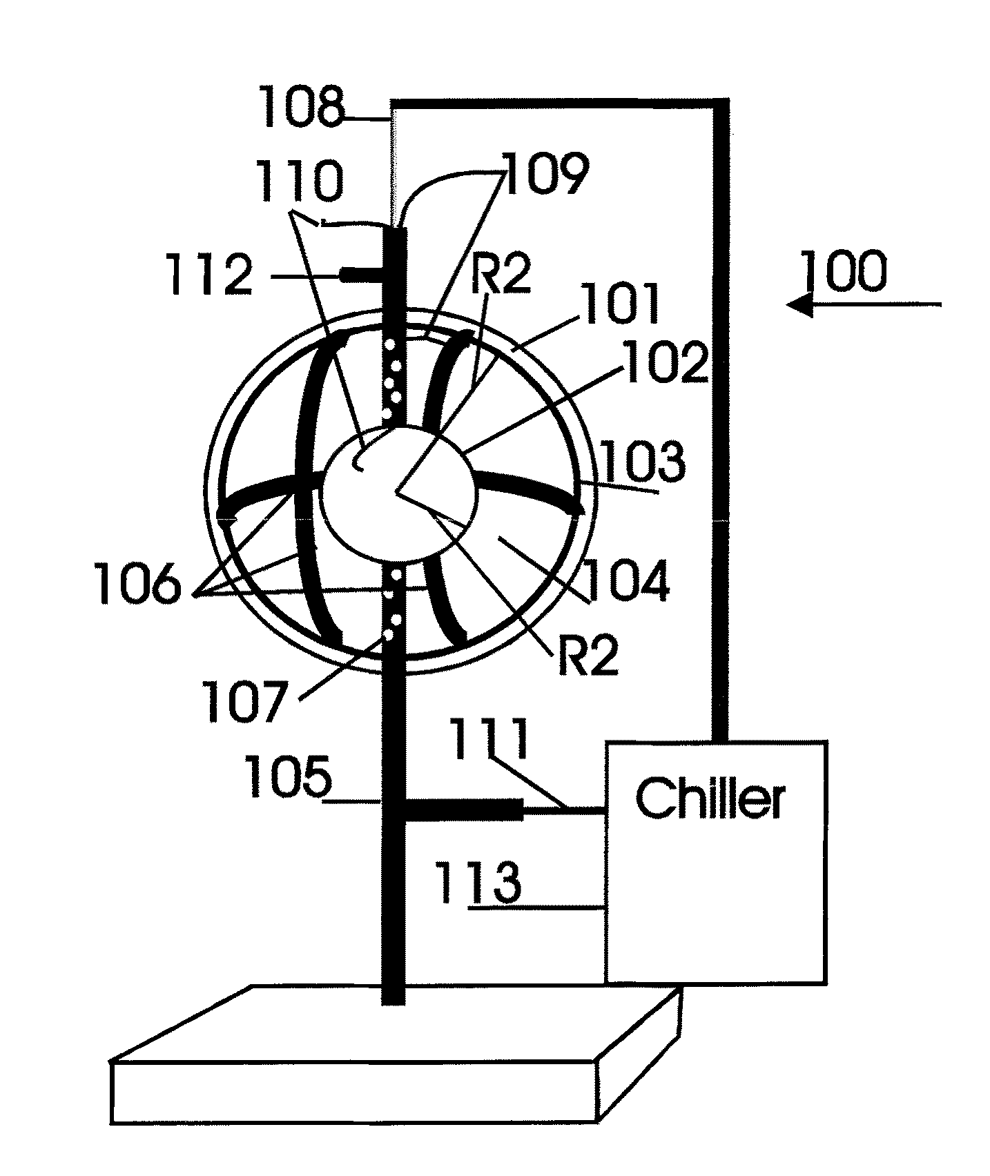
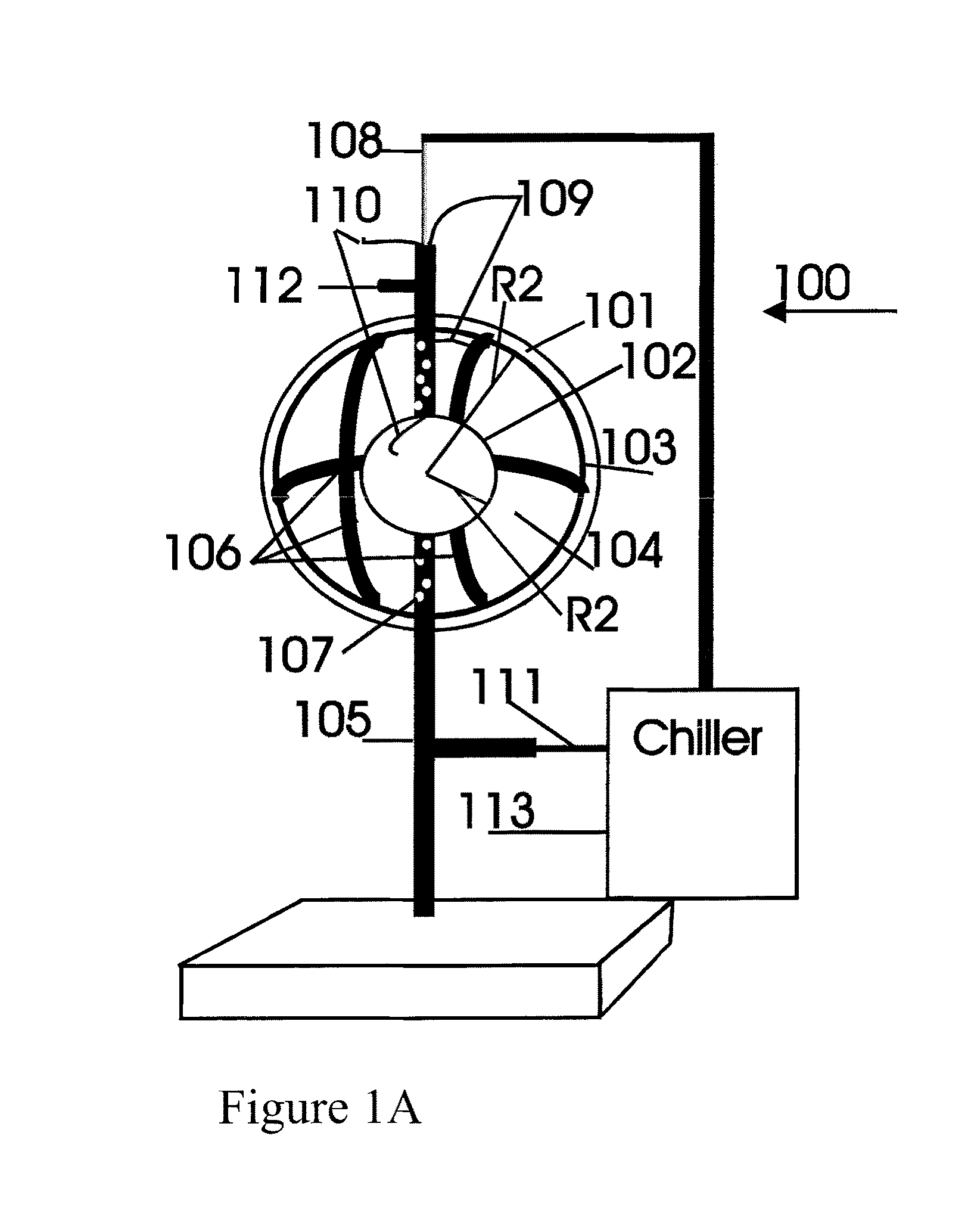
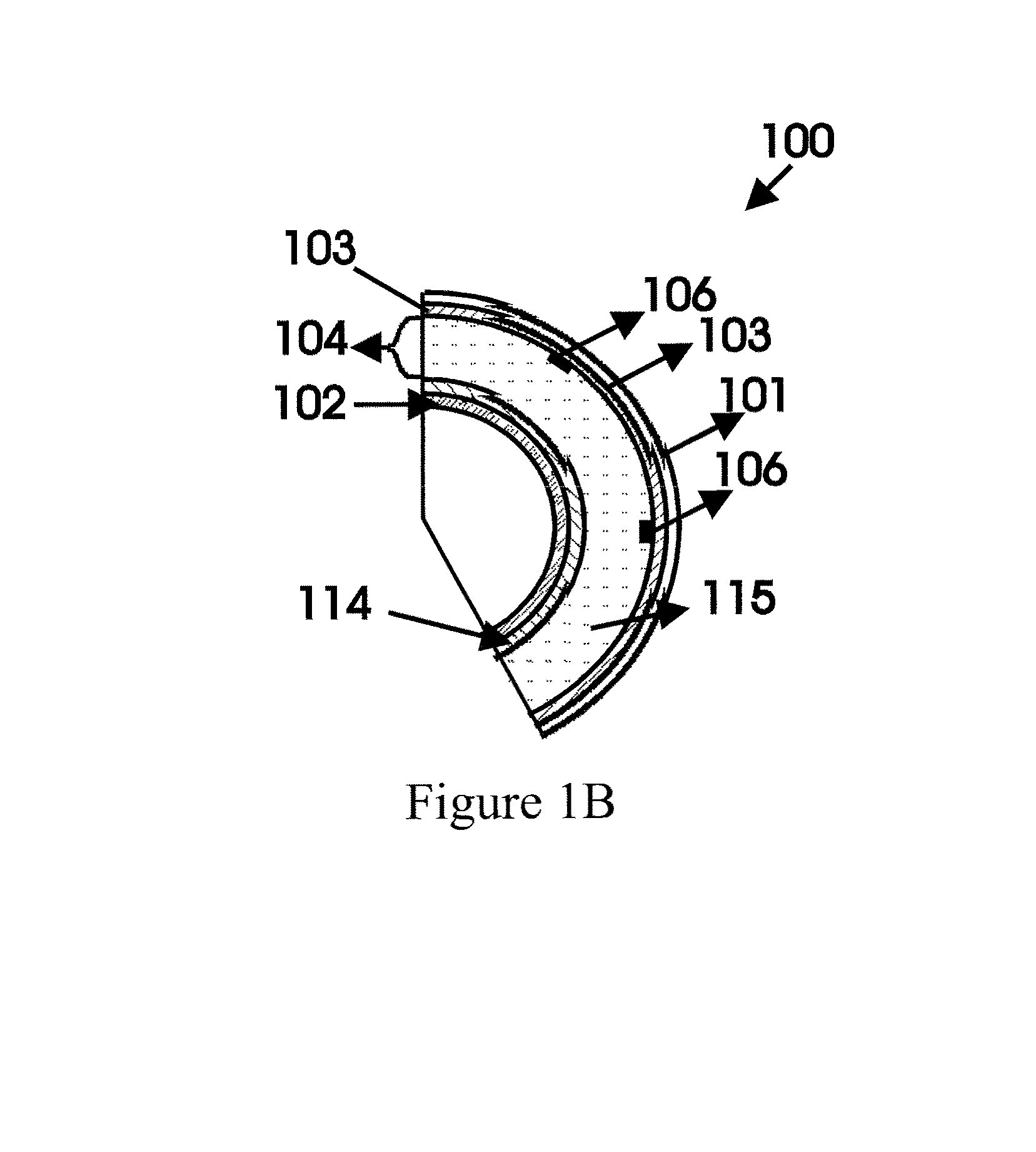
[0047]A first embodiment of a scalable spherical laser 100 is shown in FIGS. 1A and 1B. The laser 100 is applicable for use with active amplifying media that do not rely upon vessel sidewall collisions for population inversion. These include molecular, chemical, and similar active media. The spherical laser 100 includes an outer, hollow, vessel-like, generally spherical body 101 (“outer sphere”) and an inner, hollow, generally spherical vessel 102 (“inner sphere”). The inner and outer spheres may be concentric. The outer sphere 101 is occasionally referred to herein as the output coupler (“OC”) of the laser 100. The outer sphere 101 (shown in cross section in FIG. 1 to illustrate internal components) has a radius R1 greater than that of a radius R2 of the inner sphere 102, e.g., R1>R2. The sph...


PUM


Abstract

A spherical laser includes a transparent or semi-transparent outer spherical vessel having an internal cavity, an amplifying medium in the cavity, and means to excite the amplifying medium. The sphere is provided with a partially reflective coating to act as a spherical optical resonator. The spherical resonator includes a plurality of optically different regions containing alternative optical media from the cavity medium differing in bulk optical parameters utilized for mode tailoring. The optically different regions work collectively to exclude the whispering gallery modes from those supported by the spherical cavity. Excitation of the amplifying medium produces an optical gain. When the gain exceeds cavity losses and threshold conditions are met, lasing is supported. This creates a three-dimensional, spherically radiating emission, emulating a point source. The sphere is enclosed within a mirrored ellipse to image the output to a point, or within a mirrored parabola to columinate the emission.

Description

FIELD OF THE INVENTION[0001]The present invention relates to coherent light generators and, more particularly, to coherent light generations having a spherical resonant cavity.BACKGROUND OF THE INVENTION[0002]Modern lasers including semiconductor lasers, gas lasers, chemical lasers, and solid state lasers utilize optical cavities consisting of two mirrors or prisms arranged to form closed optical paths of low loss, into which an amplifying medium is inserted. The amplifying medium enclosed within the optical cavity may be gaseous, liquid, crystalline, or a glassy solid. Laser oscillation will occur at specific frequencies if the gain of the medium exceeds cavity losses. Gain of the medium is dependent upon the stimulated emission rate, which is increased when population inversion is present (a necessary condition for lasing). The onset of laser oscillation is governed by threshold conditions and stabilizes at a level that depends on the saturation intensity of the amplifying medium ...

Claims


Application Information

Patent Timeline
IPC IPC(8): H01S3/08H01S3/09H01S3/04
CPCH01S3/08H01S3/0071H01S3/0407H01S3/08081H01S3/0941H01S3/2222H01S2301/02
Inventor LACOMB, RONALD
Owner LACOMB RONALD
Why Eureka
Try Eureka