
Stress absorbing flexible heart valve frame

a flexible, heart valve technology, applied in the field of prosthetic heart valves, can solve the problems of increasing the pressure drop through, and achieve the effect of enhancing the flexibility of the cusp and facilitating the supra-annular attachment of the prosthetic valv

Active Publication Date: 2006-10-12
EDWARDS LIFESCIENCES CORP
View PDF46 Cites 106 Cited by
  • Summary
  • Abstract
  • Description
  • Claims
  • Application Information

AI Technical Summary

Benefits of technology

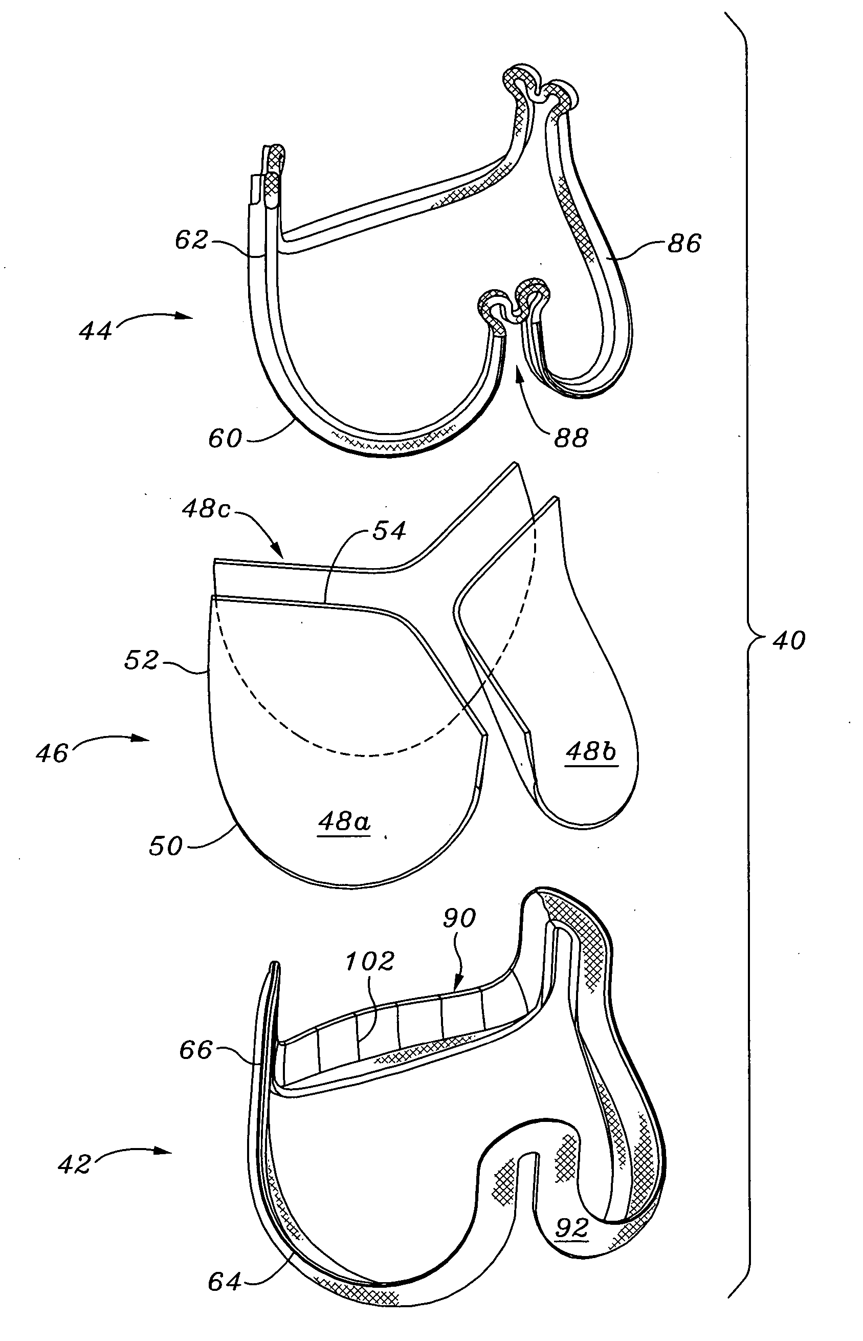
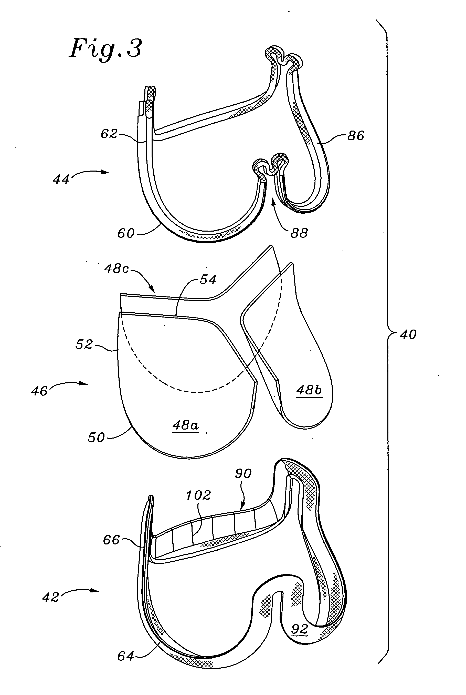
[0015] The present application further discloses a connecting band for a flexible heart valve that improves on earlier designs. In one embodiment, the connecting band features relief slits on the inner curvature of the cusps to facilitate flexing thereof. In another embodiment, the connecting band includes a more robust construction on the inflow side thereof that facilitates a supra-annular implant technique.
[0018] In accordance with another aspect of the invention, a suture-permeable connecting band for securing a prosthetic heart valve to an anatomical cavity, comprises a flexible, continuous connecting band having an inflow end and an outflow end. The connecting band exhibits an undulating shape generally circumscribing a tube with alternating inflow cusps and outflow commissures, the cusps having large radii of curvatures relative to the commissures. An inflow edge of the connecting band substantially conforms to an outflow edge thereof and follows the undulating shape such that axial gaps are created between adjacent cusps at the commissures, the gaps having a height of at least about 50% of the overall axial height of the connecting band. A continuous sewing ridge is provided around the periphery of the connecting band that is radially-outwardly directed at the commissures and larger and angled radially outward and toward the inflow end at the cusps. The sewing ridge facilitates supra-annular attachment of the prosthetic valve.
[0020] A method of supra-annular implantation of a flexible aortic prosthetic heart valve is also provided by the present invention. The method includes providing a flexible aortic prosthetic heart valve having a supporting structure to which prosthetic leaflets attach and project radially inward and to which a connecting band attaches and projects generally radially outward. The supporting structure and connecting band each generally circumscribe a tube and has an undulating shape with alternating inflow cusps and outflow commissures. The cusps have large radii of curvatures relative to the commissures. An inflow edge of the valve substantially conforms to an outflow edge thereof and follows the undulating shape such that axial gaps are created between adjacent cusps at the commissures. The gaps have a height of at least about 50% of the overall axial height of the supporting structure, and a continuous outwardly directed sewing ridge facilitates supra-annular attachment of the prosthetic valve. The method includes first removing the native leaflets at their line of attachment, then delivering the prosthetic heart valve to an aortic annulus, and finally implanting the prosthetic heart valve to the aortic annulus by securing the connecting band exclusively to fibrous tissue along the line of native leaflet attachment.
[0021] Each cusp of the connecting band may have a varying cross-section between adjacent commissures that includes at least one relief point at which the cross-section abruptly reduces such that bending of each connecting band cusp occurs first at the relief point. The relief point in each connecting band cusp may comprise a generally radial slit. Alternatively, the relief point in each connecting band cusp comprises a generally radial groove, and wherein an inflow edge of each connecting band cusp comprises at least two generally radially-directed ribs separated by the generally radial groove. In any event, the method includes securing the commissures of the prosthetic valve to the fibrous native leaflet commissures such that the valve cusps are subjected to bending forces in use and the radial slit or radial groove enhances flexibility of the cusps.

Problems solved by technology

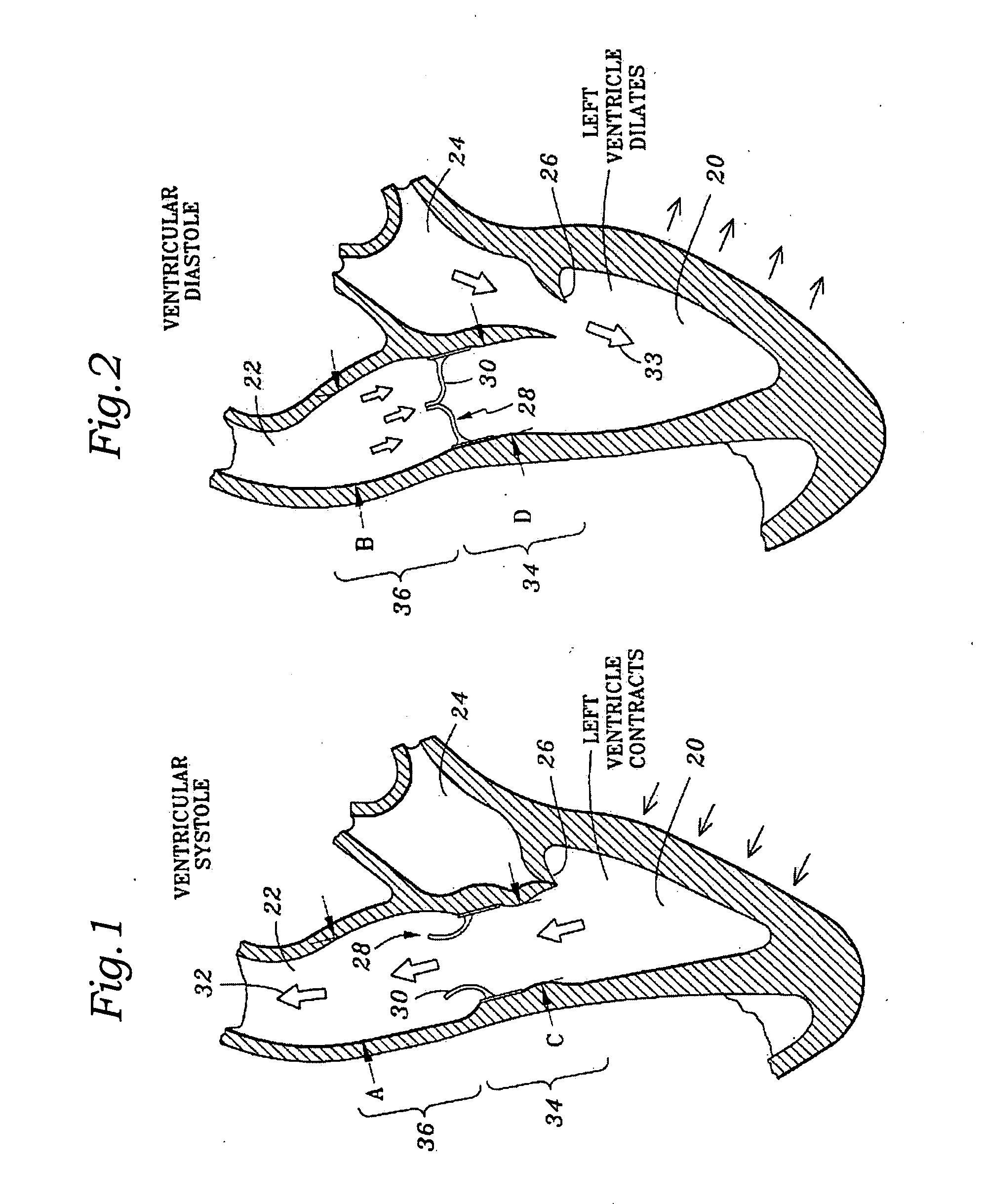
Because of the inherent rigidity in conventional heart valves, the natural dilatation of the annulus is restricted, imposing an artificial narrowing of the orifice, and increasing the pressure drop therethrough.

Method used


Image

  • Stress absorbing flexible heart valve frame
  • Stress absorbing flexible heart valve frame
  • Stress absorbing flexible heart valve frame

Examples


Embodiment Construction

[0051] The present invention provides a sewing ring or connecting band for a highly flexible aortic heart valve that is attached generally along a scalloped or undulating perimeter downstream from where the natural leaflets were originally attached. The natural leaflets include arcuate cusp portions separated by common commissure portions. If the natural valve has three leaflets, and has a vertically oriented flow axis, the leaflets are evenly distributed circumferentially 1200 apart with lower (upstream) cusp portions and upper (downstream) generally axially aligned commissure portions. The annular root of the native aortic valve is composed of fibrous tissue and generally conforms to the undulating perimeter of the valve to support the leaflets. In this respect, implanting a prosthetic aortic heart valve of the present invention involves typically excising the natural leaflets and then attaching the prosthetic heart valve proximate the fibrous annulus. Certain embodiments may be a...


PUM


Abstract

A flexible support frame for a prosthetic heart valve having commissure tips that are shaped to even out stresses imposed during use. The support frame is an elongated wire-like element formed by a plurality, typically three, of arcuate cusp regions on an inflow end alternating with the same number of commissures terminating in tips on an outflow end. The commissure tips are elongated relative to more simple shapes. The commissure tips may be shaped with a complex curve having two enlarged convex flexure portions separated by a concave bridge portion at the midpoint of the commissure tip. The support frame may be fabricated by separating a two-dimensional blank from a sheet and then converting the blank into a three-dimensional support frame shape. The cross-sectional thickness of the support frame may be variable, such as by adjusting the thickness of the pattern of the two-dimensional blank in the sheet. Desirably, the radial thickness remains constant while the circumferential dimension varies with a maximum located at the commissure tips.

Description

RELATED APPLICATION(S) [0001] The present application is a continuation-in-part of co-pending U.S. application Ser. No. 11 / 099,706, filed Apr. 6, 2005, entitled “HIGHLY FLEXIBLE HEART VALVE CONNECTING BAND,” the disclosure of which is expressly incorporated by reference herein.FIELD OF THE INVENTION [0002] The present invention relates to prosthetic heart valves, and, more particularly, to a highly flexible prosthetic tissue valve and associated support frame. BACKGROUND OF THE INVENTION [0003] Prosthetic heart valves are used to replace damaged or diseased heart valves. In vertebrate animals, the heart is a hollow muscular organ having four pumping chambers: the left and right atria and the left and right ventricles, each provided with its own one-way outflow valve. The natural heart valves are identified as the aortic, mitral (or bicuspid), tricuspid and pulmonary valves. The valves of the heart separate chambers therein, and are each mounted in an annulus therebetween. The annulu...

Claims


Application Information

Patent Timeline
IPC IPC(8): A61F2/24
CPCA61F2/2409A61F2/2418A61F2220/0066A61F2220/005A61F2220/0075
Inventor MARQUEZ, SALVADOR
Owner EDWARDS LIFESCIENCES CORP
Learn More