Programmable controller system

a controller and programming technology, applied in the field of programming controllers, can solve the problems of more difficult to uncover the cause of abnormality, disconnection of connecting cables, miswiring, etc., and achieve the effect of reducing the time required for uncovering abnormal communication

Active Publication Date: 2006-10-12
ORMON CORP
View PDF3 Cites 6 Cited by
  • Summary
  • Abstract
  • Description
  • Claims
  • Application Information

AI Technical Summary

Benefits of technology

[0028] According to such a constitution, when the abnormal communication occurs between the development support device and the target programmable controller, the abnormal place can be specified quickly.
[0029] According to the present invention, in the PLC system where when PLC is connected via a network, PLC can be monitored, a program can be edited and parameters can be set without requiring switching of the physical connection of a communication cable, when the abnormal communication such that communication cannot take place via a network, the time required for uncovering the abnormal communication can be shortened.

Problems solved by technology

In such a method, however, the computer should be brought around the PLC which is desired to be monitored each time, and thus this method is inconvenient.
With the above publicly-known technique, in the case where the other PLCs on the network (hereinafter, target PLCs) are monitored via the PLC, even if communication cannot take place between the computer and the target PLC, it is quite difficult to find a place on a communication path between the computer and the target PLC where abnormality occurs.
Particularly, in the case where the communication path covers a plurality of networks, it is more difficult to uncover the cause for the abnormality.
The trouble between the personal computer and the relay PLC includes (1) disconnection of the connecting cable and mis-wiring, (2) an error in communication specification to be set on the side of the personal computer, (3) mis-setting of a communication port of the relay PLC, and the like.
The trouble between the relay PLC and the target PLC includes (1) the disconnection of the connecting cable on the communication path, (2) mis-setting of a routing table previously stored in the PLC on the communication path, (3) communication time-out due to communication load of the network on the communication path, and the like.
On the other hand, when communication cannot take place via the network, it takes a very long time to uncover causes for it due to a complicated network path or variety of cause items.
In a network where the PLC system is now being constructed, however, the setting of a routing table itself occasionally has a problem.
At this time, each setting of the PLCs should be checked one by one, and thus it takes a very long time to solve the problem.

Method used


Image

  • Programmable controller system
  • Programmable controller system
  • Programmable controller system

Examples


Embodiment Construction

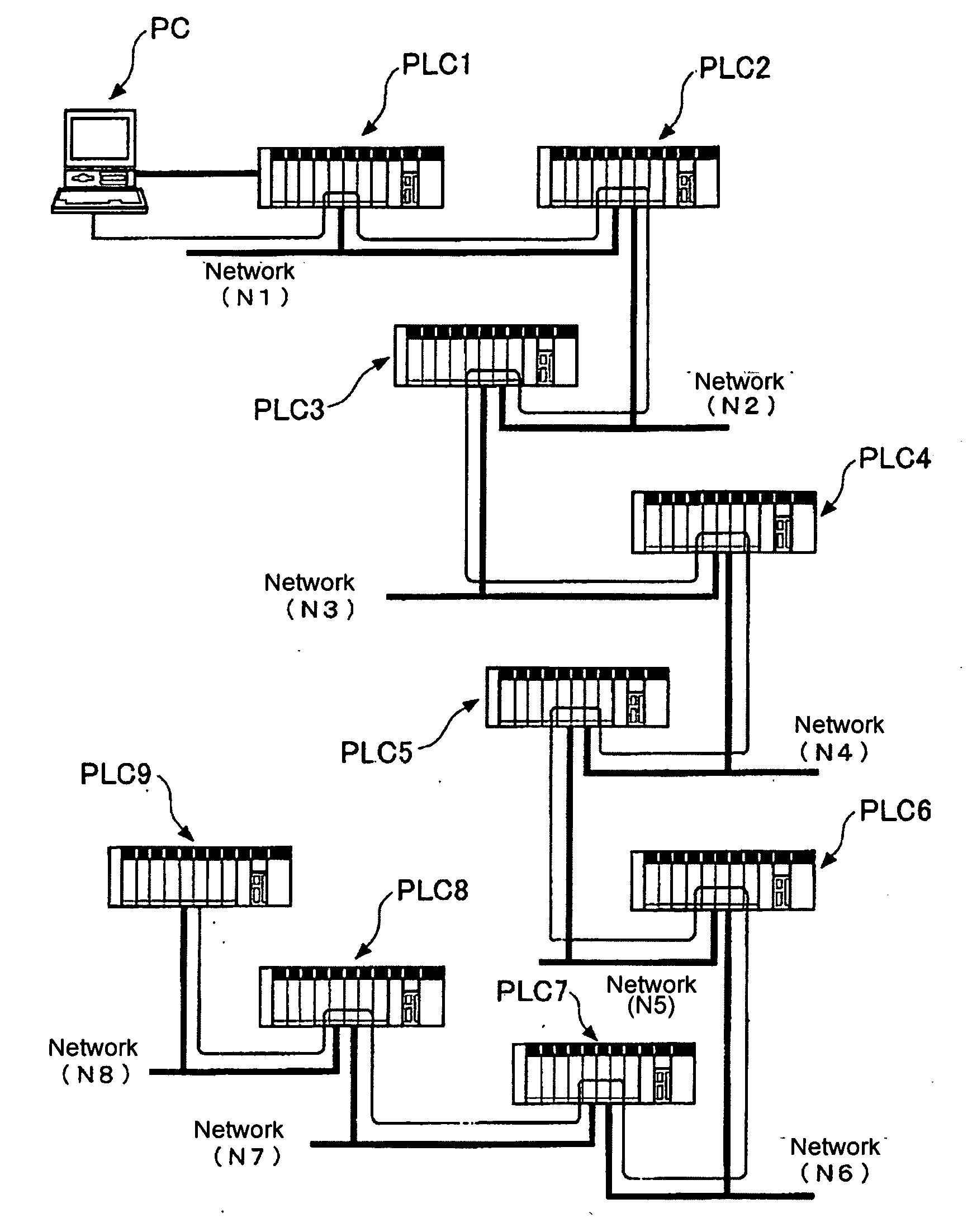
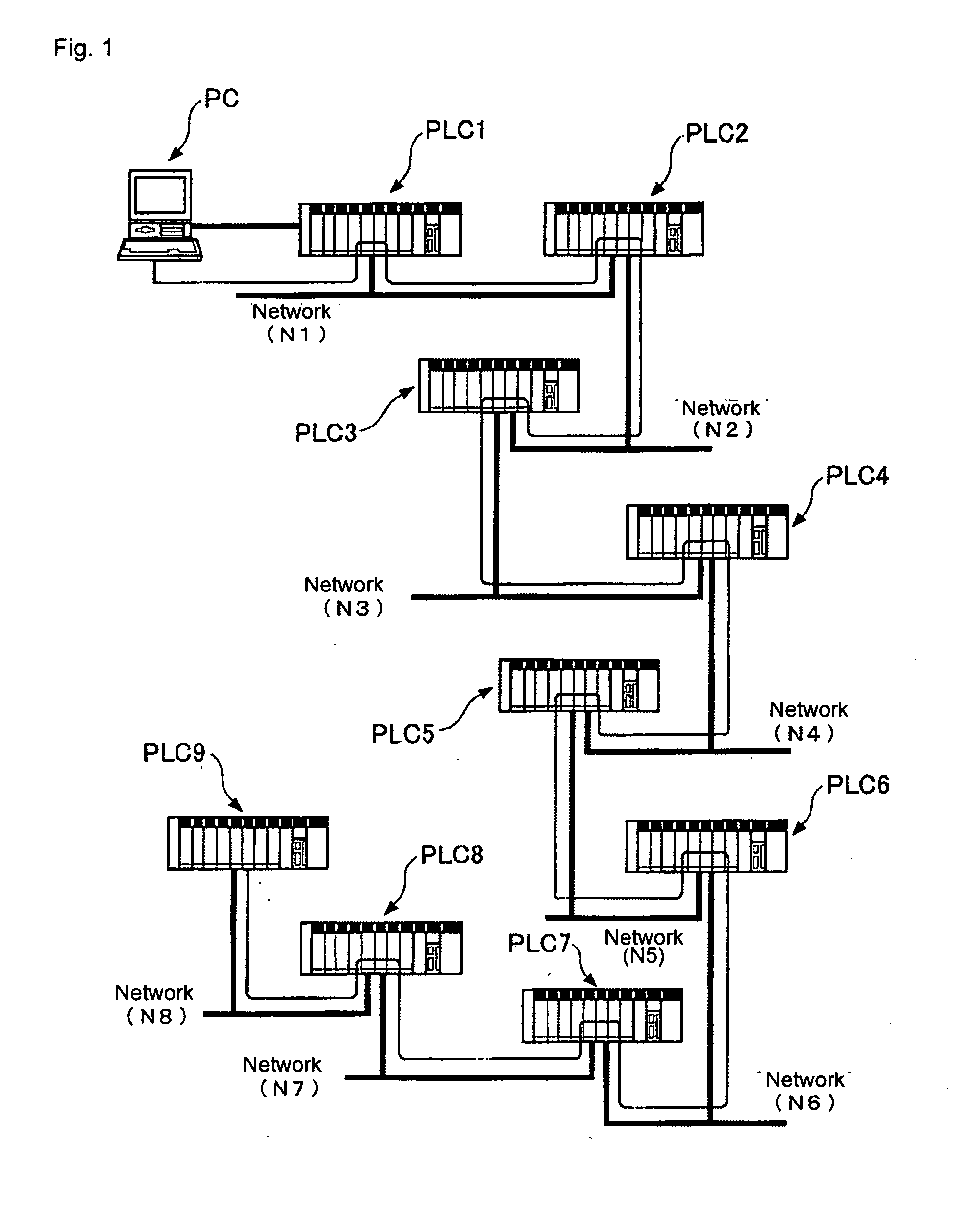
[0043] A preferred embodiment of the present invention is explained in detail below with reference to the accompanying drawings. FIG. 1 shows one example of a network constitutional diagram of a PLC network to which the present invention is applied.

[0044] As shown in FIG. 1, the PLC system includes nine PLCs (PLC1 to PLC9). These PLCs (PLC1 to PLC9) are connected via eight system networks (N1 to N8). That is to say, the PLC1 and the PLC2 are connected via the network N1. The PLC2 and the PLC3 are connected via the network N2. The PLC3 and the PLC4 are connected via the network N3. The PLC4 and the PLC5 are connected via the network N4. The PLC5 and the PLC6 are connected via the network N5. The PLC6 and the PLC7 are connected via the network N6. The PLC7 and the PLC8 are connected via the network N7. The PLC8 and the PLC9 are connected via the network N8. Network addresses are given as information for uniquely specifying the individual networks to the networks composing the PLC sys...


PUM


Abstract

A programmable controller system comprises networks including a plurality of programmable controllers and a development support device. One of the programmable controllers is set as a relay programmable controller. The development support device is used by online-connecting to the relay programmable controller via a communication line and by switching connecting destination to a target programmable controller on the networks during a state of online-connecting to the relay programmable controller.

Description

BACKGROUND OF THE INVENTION [0001] 1. Field of the Invention [0002] The present invention relates to a programmable controller (hereinafter, PLC) system in which a plurality of PLCs are connected via a network. [0003] 2. Description of the Related Art [0004] In the case where a plurality of PLCs connected to a network are monitored, a computer (development support device) having a monitoring function is connected directly to a PLC which is desired to be monitored via a communication cable. In such a method, however, the computer should be brought around the PLC which is desired to be monitored each time, and thus this method is inconvenient. [0005] A technique such that a computer is connected only to one PLC on the network and the other PLCs on the network are monitored via the one PLC is, therefore, known. (See, for example, Japanese Patent Application Laid-Open No. 2000-47717.). [0006] With the above publicly-known technique, in the case where the other PLCs on the network (herei...

Claims


Application Information

Patent Timeline
Patent Type & Authority Applications(United States)
IPC IPC(8): G06F3/00
CPCG05B19/052G05B19/4185G05B2219/1204H04L45/54G05B2219/33228H04L45/00G05B2219/31131Y02P90/02
Inventor SHIRANE, KAKUTO
Owner ORMON CORP
Why Eureka
Try Eureka