Production installation

a production installation and installation method technology, applied in the direction of measurement/indication equipment, pile separation, other manufacturing equipment/tools, etc., can solve the problem of very complex construction of conventional production installations, and achieve the effect of simple design, simple and flexible manner, and reduced downtim

Inactive Publication Date: 2006-10-19
CROSS HULLER
View PDF15 Cites 3 Cited by
  • Summary
  • Abstract
  • Description
  • Claims
  • Application Information

AI Technical Summary

Benefits of technology

[0016] In the further development, according to which two workpiece grippers are disposed on the loading means, a workpiece gripper can be used for transporting workpieces to be processed and the other workpiece gripper can be used for transporting processed workpieces. This reduces the downtimes, i.e. the inoperative times of the processing machines.
[0017] The design of the supply transport means, the discharge transport means, the storage transport means, the transfer transport means, and the cooperating loading means supplies the workpieces to be processed, repositions these workpieces and discharges the processed workpieces in a very simple and flexible manner. The described transport means may be of very simple design. Both parallel and sequential processing are possible, i.e. the same processing procedures can be simultaneously performed on different workpieces at several processing machines or different processing procedures can be sequentially performed at the processing machines on the same workpiece.

Problems solved by technology

These conventional production installations are of very complex construction.

Method used


Image

  • Production installation
  • Production installation
  • Production installation

Examples


Embodiment Construction

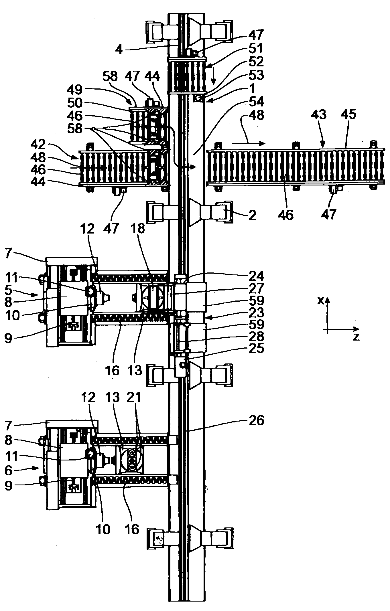
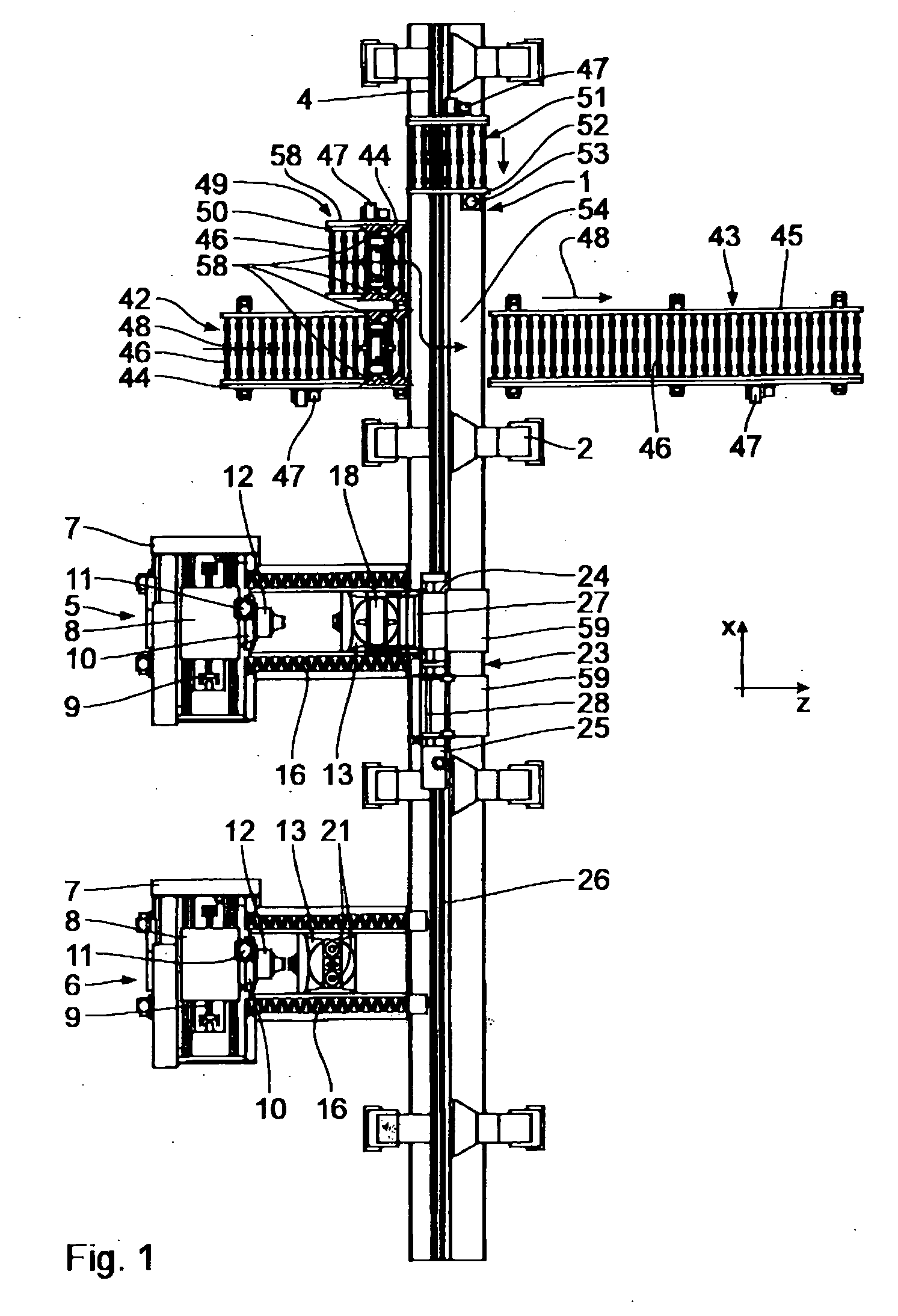
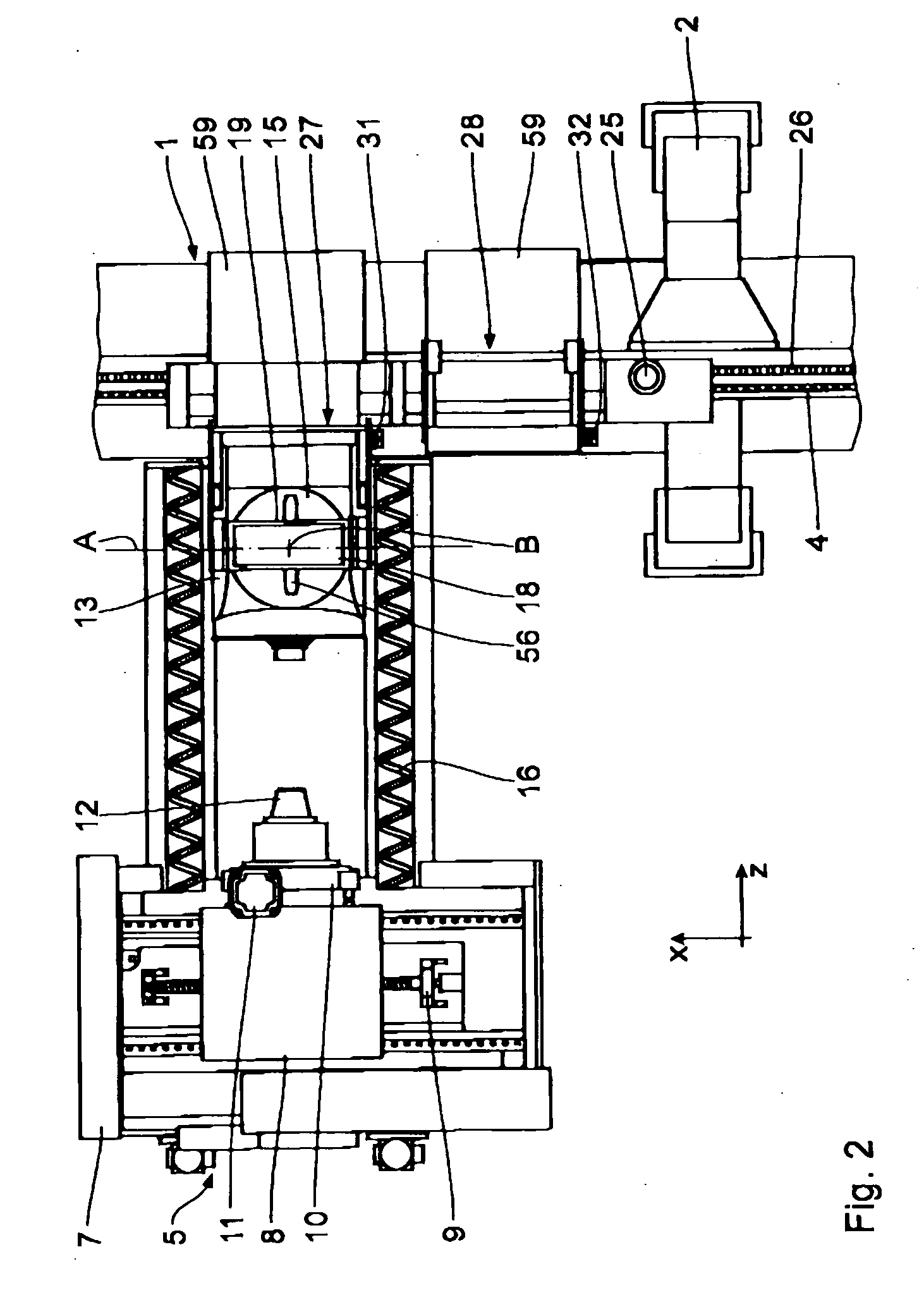
[0027] The production installation shown in the drawing comprises a loading transport means 1 having a transport rail 4 which is supported on the floor 3 via supports 2.

[0028] Processing machines 5, 6, in the present case machine tools, are disposed on one side (left hand side of FIG. 1) of the loading transport means 1. They comprise a machine frame 7 on which an x carriage 8 is disposed which can be displaced horizontally, parallel to the longitudinal direction of the transport rail 4, using a ball roll spindle drive 9. A carriage 10 is disposed on the side of the x carriage 8 facing the loading transport means 1 and can be vertically displaced by a ball roll spindle drive 11. A tool spindle 12 is disposed on the y carriage 10, which cannot be displaced in the z direction (i.e. horizontal, transverse to the x direction and perpendicular to the longitudinal direction of the transport rail 4). A workpiece carriage 13 is disposed on the machine frame 7 such that it can be displaced ...


PUM

PropertyMeasurementUnit
displacementaaaaaaaaaa
distanceaaaaaaaaaa
flexibleaaaaaaaaaa

Abstract

A production installation comprises a loading transport means with a transport rail connecting processing machines. It also comprises workpiece grippers for supplying the processing machines with workpieces to be processed and for removing processed workpieces from the processing machines. The workpiece grippers can be pivoted about only one pivot axis between a lowered transfer position and a pivoted-up transport position. The processing machines also comprise a workpiece carriage which can be displaced transversely with respect to the direction of the transport rail for transport between the workpiece gripper and processing position on the processing machine.

Description

BACKGROUND OF THE INVENTION [0001] 1. Field of the Invention [0002] The invention concerns a production installation [0003] with several processing machines which are disposed next to each other in a row; [0004] with a loading transport means which comprises [0005] a transport rail connecting the processing machines, [0006] at least one loading means which is movable on the transport rail; and [0007] at least one workpiece gripper disposed on the loading means for supplying the processing machines with workpieces to be processed and for removing processed workpieces from the processing machines; [0008] with a supply transport means for supplying workpieces to be processed to the loading transport means in a transport direction, transverse to the direction of the transport rail; and [0009] with a discharge transport means for unloading processed workpieces from the loading transport means in a transport direction transverse to the direction of the transport rail. [0010] 2. Background...

Claims


Application Information

Patent Timeline
Patent Type & Authority Applications(United States)
IPC IPC(8): B23P23/00
CPCB23Q7/1415B23Q7/1431Y10T29/5196Y10T29/5124B23Q41/02B23Q7/00B23Q7/04B23Q7/14
Inventor STENGELE, GERALDNUSSBAUM, JORG-MICHAELCORBEAN, IOAN-MIRCEA
Owner CROSS HULLER
Why Eureka
Try Eureka