
Steering device

a steering device and steering column technology, applied in the direction of steering column, steering device, steering parts, etc., can solve the problems of large steering device, time-consuming assembly, and large number of components, and achieve the effect of reducing sliding noise, simple assembly and small number of components

Inactive Publication Date: 2006-10-19
YAMADA SEISAKUSHO KK
View PDF16 Cites 16 Cited by
  • Summary
  • Abstract
  • Description
  • Claims
  • Application Information

AI Technical Summary

Benefits of technology

[0005] However, in the configuration seen in Japanese Patent Application Laid-open No. 2000-16303, bushes 83, 84 and resin sheets 91, 92 are interposed between the vehicle body side bracket 72 and the column side bracket 73. Therefore the width of the vehicle body side bracket 72 is increased, so there is a problem that the steering device itself becomes larger, and the steering column itself becomes expensive. Also, the configuration of the bushes 83, 84 is complex, with slits 83b, 84b, and projections 83c, 84c. Therefore assembly is time consuming and the number of processes increases, so on this account also the cost can increase. It is an object of the present invention to provide a steering device with a very simple structure, with good operation feeling in tilt and telescopic adjustments, that is also easily assembled.
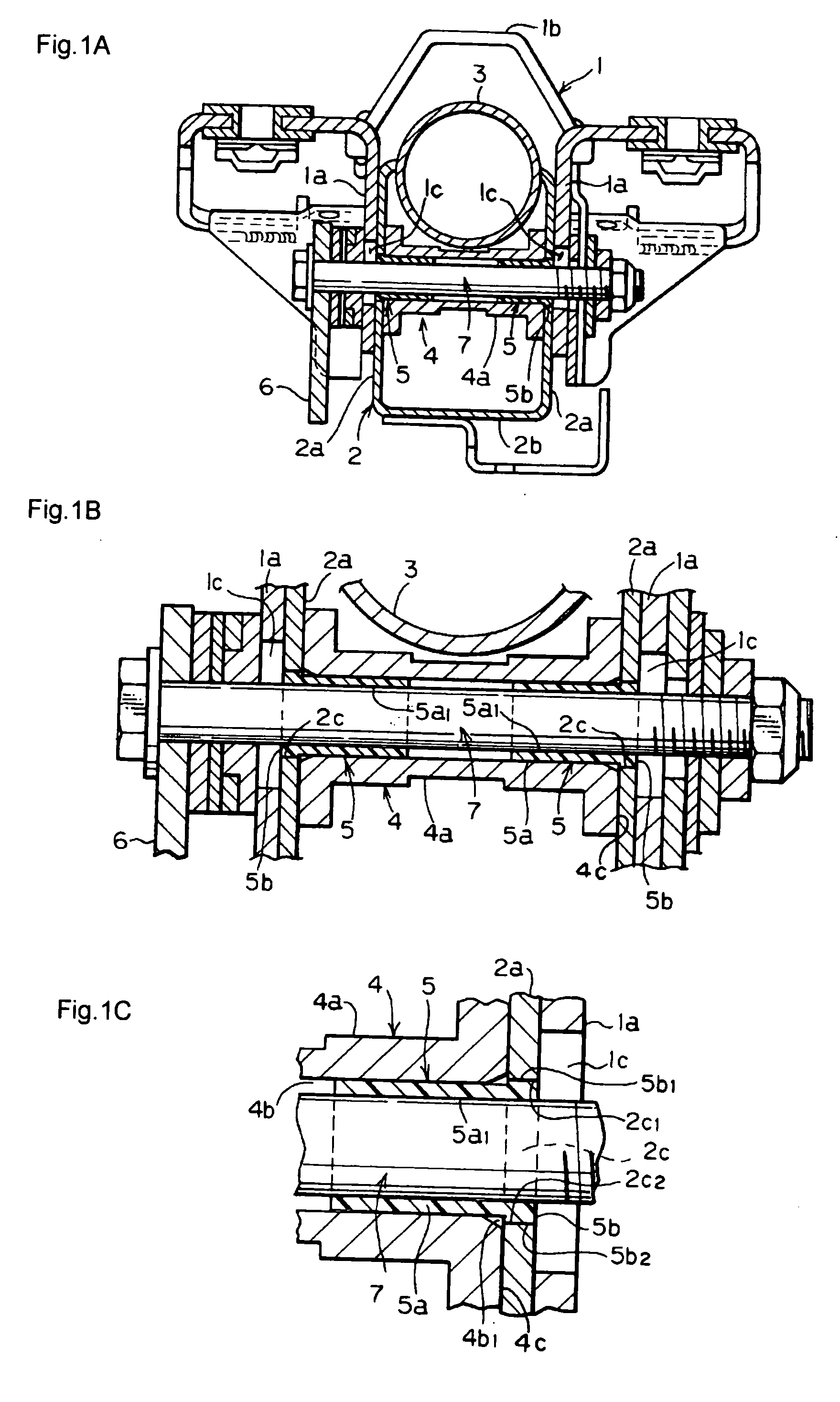
[0009] According to the invention of claim 1, shock absorber members are fitted to the collar member, and the flanges of the shock absorber members are fitted to the adjustment elongated holes, the bolt is passed through the axial through hole of the collar member and connects the fixed bracket to the movable bracket, so the movement of the movable bracket when carrying out tilt and telescopic adjustments is stabilized and smooth. Also, the configuration of the invention according to claim 2 is simple, the number of components is small, and assembly is very simple. The other effects are the same as the effects of claim 1.
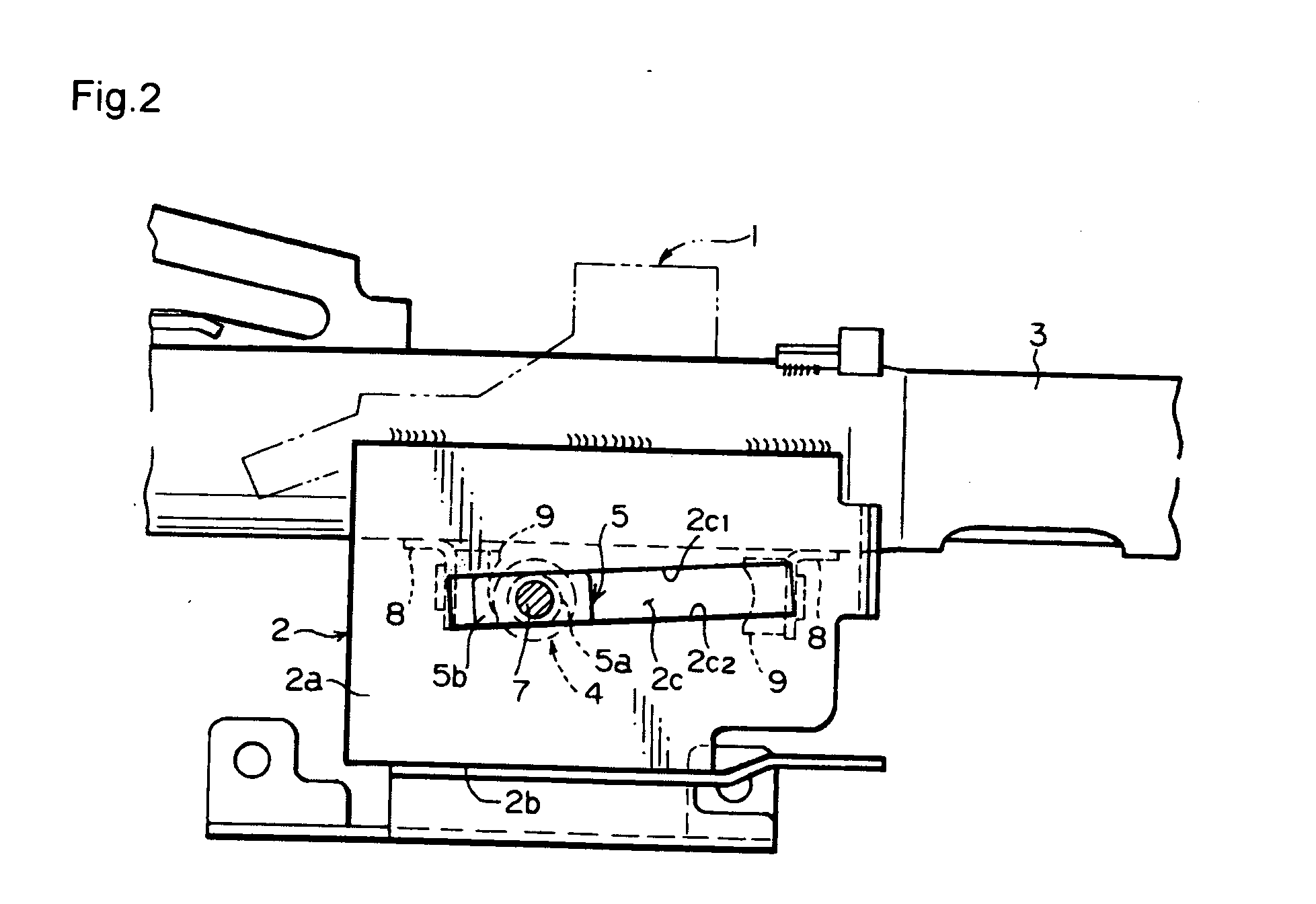
[0010] Next, according to the invention of claim 3, the thickness of the flange part of the shock absorber member is formed smaller (thinner) than the dimension of the depth of the adjustment elongated hole of the movable bracket. Therefore the flange part can be accommodated within the range of the depth of the adjustment elongated hole, so when the bolt is tightened in the tilt and telescopic adjustment mechanism, the mechanism can be securely locked. According to the invention of claim 4, the flange part of the shock absorber member is formed in an approximately rectangular shape. Therefore there is approximate plane contact conditions between the opposing two sides of the flange part and the opposing inner side edges of the adjustment elongated hole, so the sliding characteristics of the shock absorbing members in particular can be improved.
[0011] Next, according to the invention of claim 5, the shock absorbing member is made from a synthetic resin. Therefore the flange part of the shock absorbing member can slide smoothly and quietly relative to the adjustment elongated hole. Therefore sliding noise can be reduced when carrying out tilt and telescopic adjustments.

Problems solved by technology

Therefore the width of the vehicle body side bracket 72 is increased, so there is a problem that the steering device itself becomes larger, and the steering column itself becomes expensive.
Therefore assembly is time consuming and the number of processes increases, so on this account also the cost can increase.

Method used


Image

  • Steering device
  • Steering device
  • Steering device

Examples


Embodiment Construction

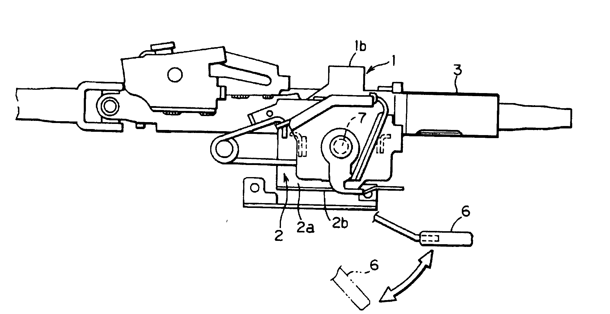
[0020] The following is an explanation of the preferred embodiments of the present invention, based upon the drawings. Firstly, as shown in FIGS. 1A, 2, 3, etc., the present invention mainly includes a fixed bracket 1, a movable bracket 2, a collar member 4, and a locking lever 6. The fixed bracket 1 includes a pair of fixed support side plates 1a, 1a on the left and right, and an installation head component 1b. The installation head component 1b is fixed to a prescribed location within a vehicle via a capsule member, and is capable of absorbing impact energy during an impact.

[0021] A pair of support side parts 2a, 2a, is formed at both sides in the width direction of the movable bracket 2, as shown in FIGS. 1A and 2. A bottom surface part 2b is formed in the bottom of the movable bracket 2 integrally connected to the pair of support side parts 2a, 2a. A steering column 3 is fitted between and fixed by welding to the tops of the pair of support side parts 2a. The pair of support si...


PUM


Abstract

To provide a steering device from which good operation feeling can be obtained in tilt and telescoping adjustments, and whose configuration is very simple. The cylindrical part formed in a pair of shock absorber members is inserted in the two end openings of an axial through hole formed in the axial direction of a collar member, flanges of the shock absorber members are slidably inserted into adjustment elongated holes formed on both sides in the width direction of a movable bracket, the movable bracket is arranged between fixed support side plates formed on both sides in the width direction of a fixed bracket. A bolt is passed through adjustment holes formed in the fixed support side plates, the adjustment elongated holes, the collar member, and the shock absorber members to be freely tightened as required.

Description

BACKGROUND OF THE INVENTION [0001] 1. Field of the Invention [0002] The present invention relates to a steering device for which good operation feeling can be obtained in tilt and telescopic adjustments, and whose configuration is very simple. [0003] 2. Description of the Related Art [0004] Conventionally, steering devices provided with tilt and telescopic adjustment mechanisms are known. In particular, in recent years importance has been placed on good operation feeling in tilt and telescopic adjustments, and many methods have been devised to reduce the noise produced during operation and to make the feeling during operation soft. One example of such a steering device is Japanese Patent Application Laid-open No. 2000-16303. This had an object to improve the sliding characteristics in the direction of telescoping. Rattle in the steering wheel is reduced mainly by interposing bushes 83, 84 and resin sheets 91, 92 between a column side bracket 73 and a vehicle body side bracket 72. SU...

Claims


Application Information

Patent Timeline
Patent Type & Authority Applications(United States)
IPC IPC(8): B62D1/16
CPCB62D1/184
Inventor SHINOHARA, EIJIHIROOKA, KOUJI
Owner YAMADA SEISAKUSHO KK
Learn More