
Jet pump assembly of a fuel system for a combustion engine

a fuel system and jet pump technology, applied in the direction of liquid fuel feeders, machines/engines, liquid fuel feed systems, etc., can solve the problems of engine starvation, electric motor fuel pump not being able to operate at full speed, etc., to improve engine cold start, improve engine reliability, and improve engine operation quiet

Active Publication Date: 2006-10-19
TI GRP AUTOMOTIVE SYST LLC
View PDF9 Cites 40 Cited by
  • Summary
  • Abstract
  • Description
  • Claims
  • Application Information

AI Technical Summary

Benefits of technology

[0005] A fuel system has a jet pump assembly which fills a fuel reservoir for providing a reliable source of adequate liquid fuel to an electric motor fuel pump located in a fuel tank for a combustion engine. The electric fuel pump preferably delivers fuel to a series of fuel injectors of the engine and at a controlled pressure. The jet pump assembly diverts a small portion of the fuel exiting the electric pump and aspirates a larger quantity of fuel from a fuel chamber defined by the fuel tank and into the reservoir. A biased closed pressure responsive valve prevents fuel flow to the venturi tube when the electric fuel pump is running under impaired conditions, thus delivering all the fuel from the electric pump to the combustion engine typically during engine cold start conditions.
[0006] Objects, features and advantages of this invention include a fuel system with a jet pump assembly which will not deprive a starting engine of full fuel output during low voltage or impaired electric motor fuel pump operation. Other advantages include a more economical and robust fuel pump module having an electric motor fuel pump which need not be designed with excess normal capacity to handle low voltage conditions, improved engine cold starts, more reliable engine starts, relatively quiet operation, and a design which is relatively simple, economical to manufacture and assemble, and requires little to no maintenance and in service has a long and useful life.

Problems solved by technology

Unfortunately, during degraded or harsh conditions such as cold engine starts or substantially low voltage conditions, the electric motor fuel pump may not be capable of operating at full speed.
When the electric pump operation is impaired, a potential exists that the engine may be starved of fuel during cold engine starts and / or low voltage conditions.

Method used


Image

  • Jet pump assembly of a fuel system for a combustion engine
  • Jet pump assembly of a fuel system for a combustion engine
  • Jet pump assembly of a fuel system for a combustion engine

Examples


Embodiment Construction

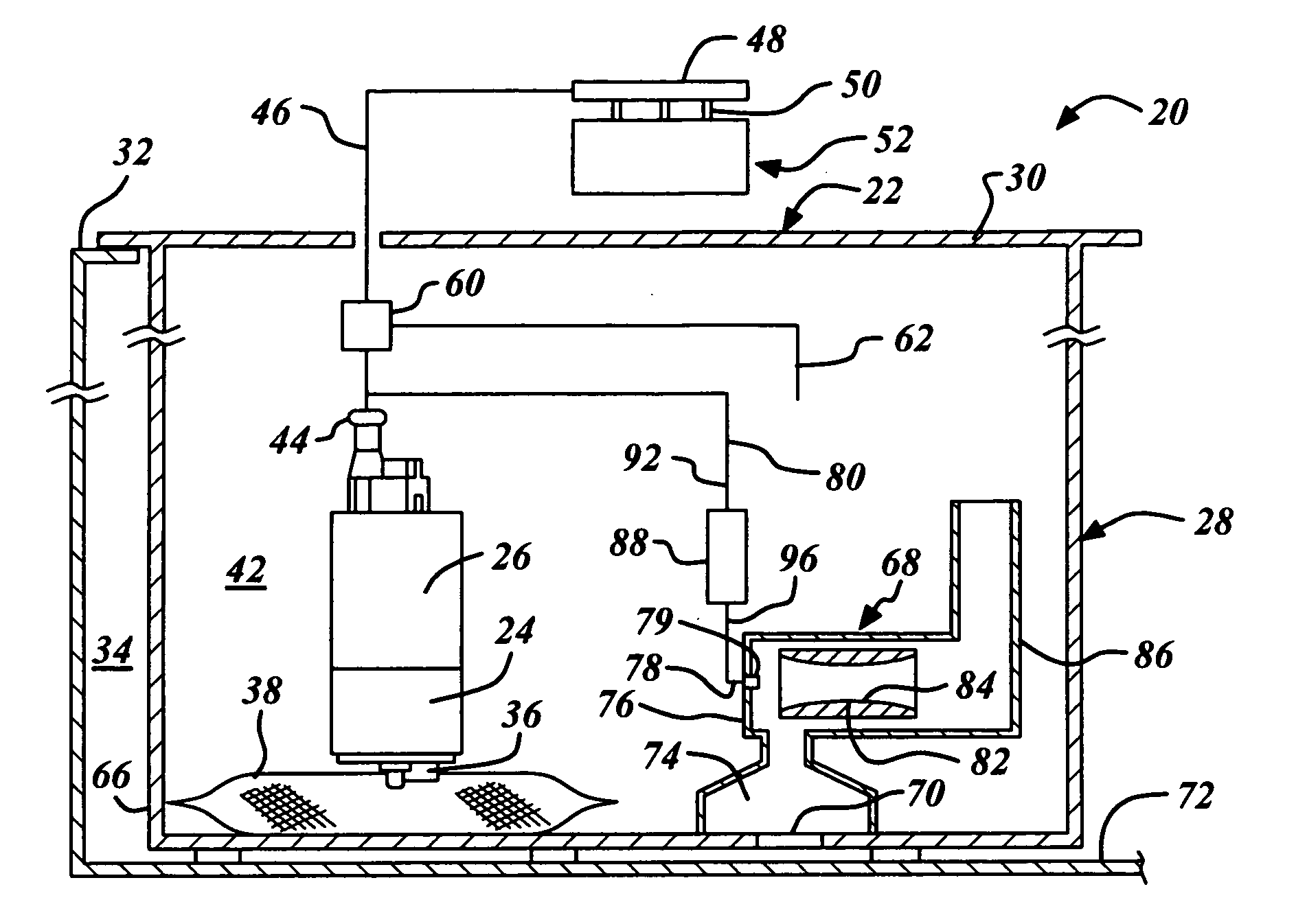
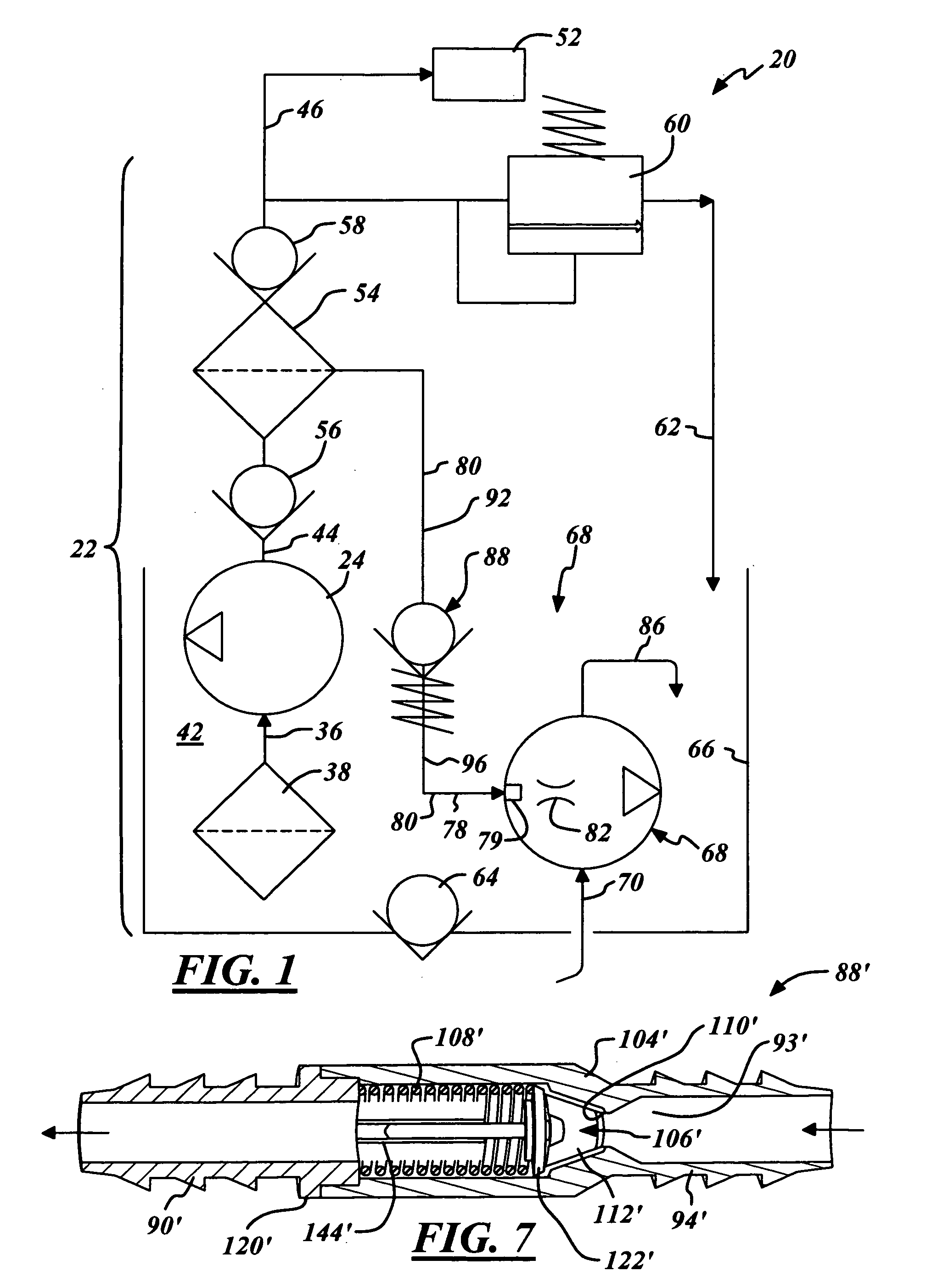
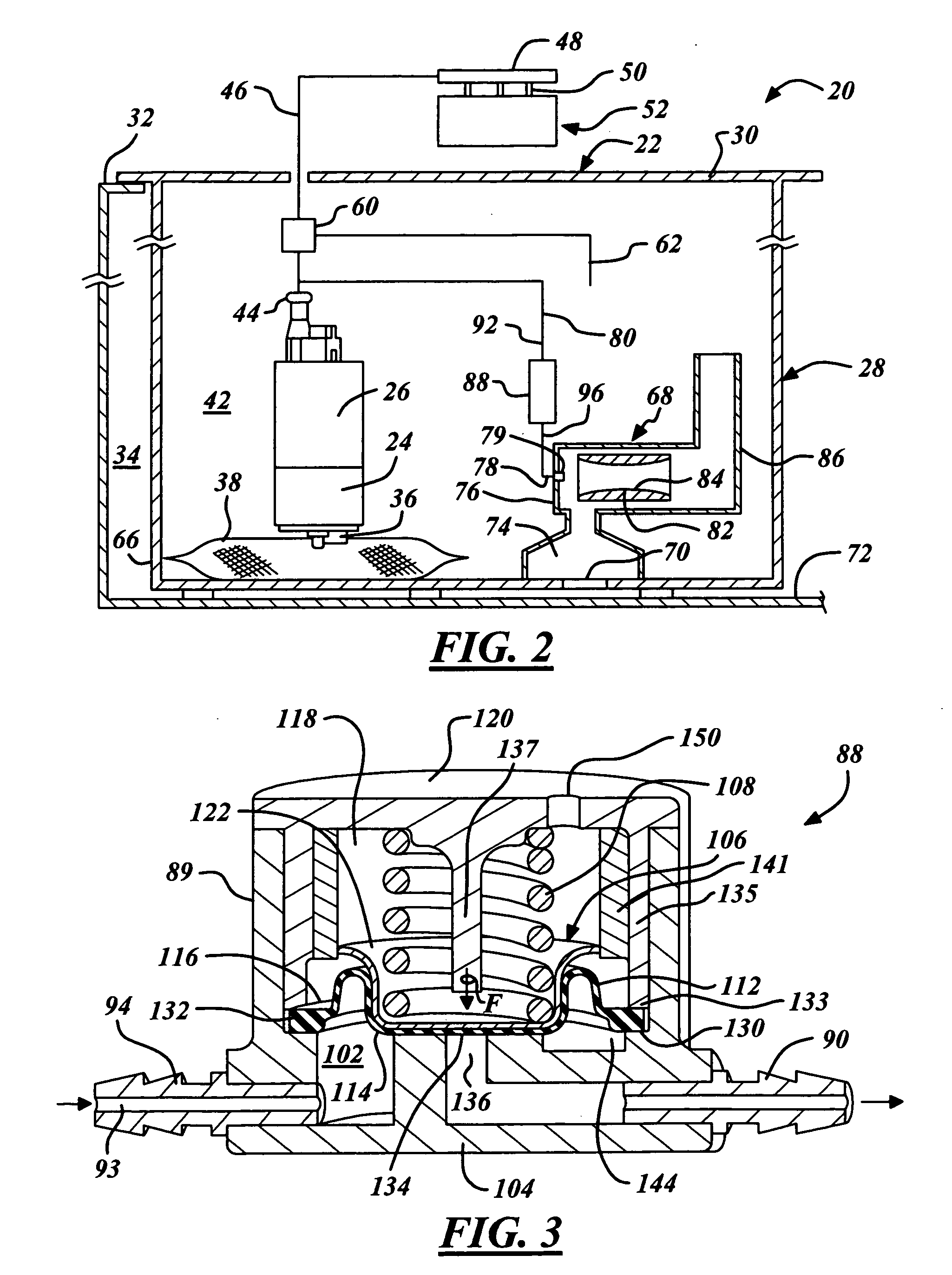
[0018] Referring in more detail to the drawings, FIGS. 1 and 2 illustrate a vehicle fuel system 20 with an in-tank fuel pump module 22 having a fuel pump 24 and an electric motor 26 supported preferably by a structure 28 that preferably includes a flange 30 engaged sealably to a fuel tank 32 that defines a fuel storage chamber 34. The fuel pump 24 has an inlet 36 that receives fuel preferably through a filter 38, capable of filtering at preferably about thirty-one microns, from a fuel reservoir or sub-chamber 42 defined by the structure 28 and disposed in the fuel storage chamber 34 of the tank 32. An outlet 44 of the fuel pump 24 delivers liquid fuel through a vehicle fuel conduit 46 to a fuel rail 48 of a combustion engine 52 having at least one fuel injector 50 for controlling fuel flow to respective combustion chambers of the engine 52. Preferably the fuel supply conduit 46 communicates with the pump outlet 44 through an outlet filter 54 disposed between two check valves 56, 58 ...


PUM


Abstract

A fuel system has a jet pump assembly that fills a fuel reservoir for providing a reliable source of fuel to an electric motor fuel pump located in a fuel tank for a combustion engine. The electric fuel pump preferably delivers fuel at a controlled pressure to a series of fuel injectors of the engine. A small portion of the fuel exiting the electric fuel pump is diverted to the jet pump assembly that aspirates fuel from the fuel tank and into the reservoir. A biased normally closed pressure responsive valve prevents fuel flow to the jet pump when the electric fuel pump is running under impaired conditions, thus providing all the fuel to the combustion engine typically during cold engine start conditions.

Description

REFERENCE TO RELATED APPLICATION [0001] Applicant claims the benefit of U.S. provisional application, Ser. No. 60 / 672,788, filed Apr. 19, 2005.FIELD OF THE INVENTION [0002] This invention relates generally to a liquid fuel system of a combustion engine of an automotive vehicle and more particularly to a jet pump assembly of the fuel system for maintaining fuel level in a reservoir disposed in a fuel tank. BACKGROUND OF THE INVENTION [0003] Electric motor fuel pumps are commonly used to supply the fuel demand for engines in a wide variety of applications. The electric fuel pump is known to be integrated into an in-tank fuel pump module typically having a filter at the pump inlet, a check valve at the pump outlet and a pressure regulator, downstream of the outlet check valve, for controlling fuel pressure at a fuel rail or fuel manifold mounted to the engine of an automotive vehicle. A support structure of the module usually includes a flange mounted sealably to the fuel tank and a re...

Claims


Application Information

Patent Timeline
IPC IPC(8): F02M37/04
CPCF02M37/106F02M37/025F02M37/00F02M37/04
Inventor PALUSZEWSKI, PAUL J.
Owner TI GRP AUTOMOTIVE SYST LLC
Features
  • Generate Ideas
  • Intellectual Property
  • Life Sciences
  • Materials
  • Tech Scout
  • Unparalleled Data Quality
  • Higher Quality Content
  • 60% Fewer Hallucinations
Learn More