Control valve structure for an oxygen machine

Inactive Publication Date: 2006-10-19
HUANG SHAO SHIH
View PDF6 Cites 2 Cited by
  • Summary
  • Abstract
  • Description
  • Claims
  • Application Information

AI Technical Summary

Benefits of technology

[0007] It is the primary object of the present invention to provide a control valve structure for an oxygen machine, which uses a motor to link a cam on a disc to rotate and controls two valve rods to move in a reciprocating movement. The design is simple and easy to operate.
[0008] It is another object of the present invention to provide a control valve structure for an oxygen machine, which operation can be controlled accurately.
[0009] It is a further object of the present invention to provide a control valve structure for an oxygen machine, which is easy to maintain.

Problems solved by technology

However, should any of the electromagnetic valves is not functioning, the air flow in sequence is broken and air flow is out of control, thus oxygen can not be produced properly.

Method used


Image

  • Control valve structure for an oxygen machine
  • Control valve structure for an oxygen machine
  • Control valve structure for an oxygen machine

Examples


Embodiment Construction

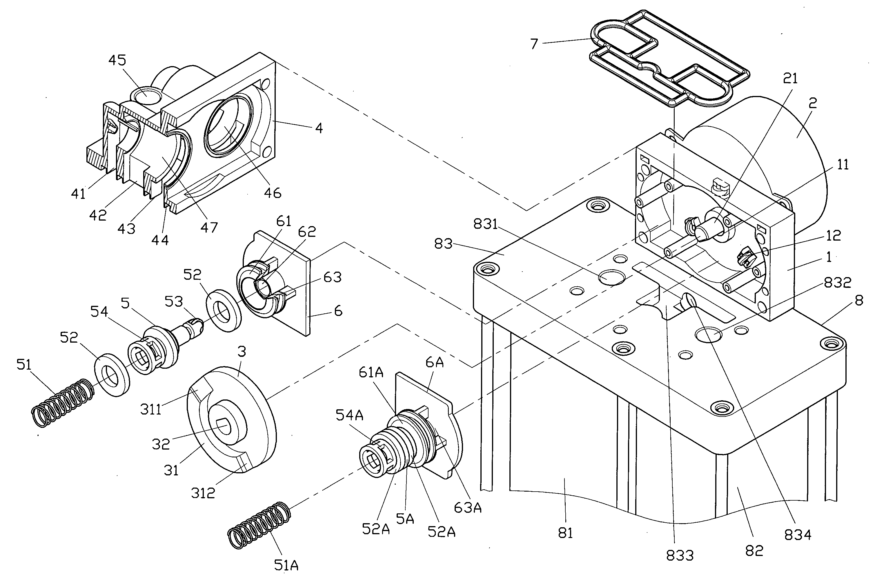
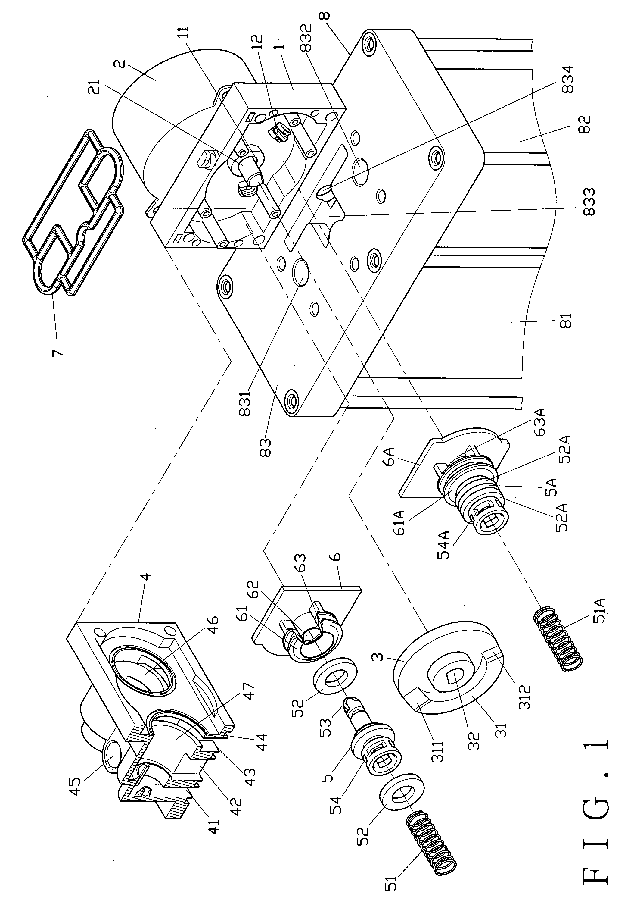
[0016] As shown in FIG. 1, the present invention comprises a valve seat 1, a motor 2, a disc 3, an air valve 4, a pair of first and second valve rods 5 and 5A, a pair of first and second valve rod seats 6 and 6A, a washer 7 and an air filter 8.

[0017] The valve seat 1 has a through hole 11 for a spindle 21 of the motor 2 to insert there through. The spindle 21 has a cut-off section at the front end. The valve seat 1 is provided with three pulleys 12 spaced from one another for the disc 3 to secure thereat.

[0018] The disc 3 has one side leaning on the pulleys 12 of the valve seat 1, while the other side of the disc 3 is formed with a half cam 31 having a first slanting surface 311 and a second slanting surface 312 on respective ends thereof, and a hole 32 at the center with a cut-off section corresponding to the cut-off section of the spindle 21.

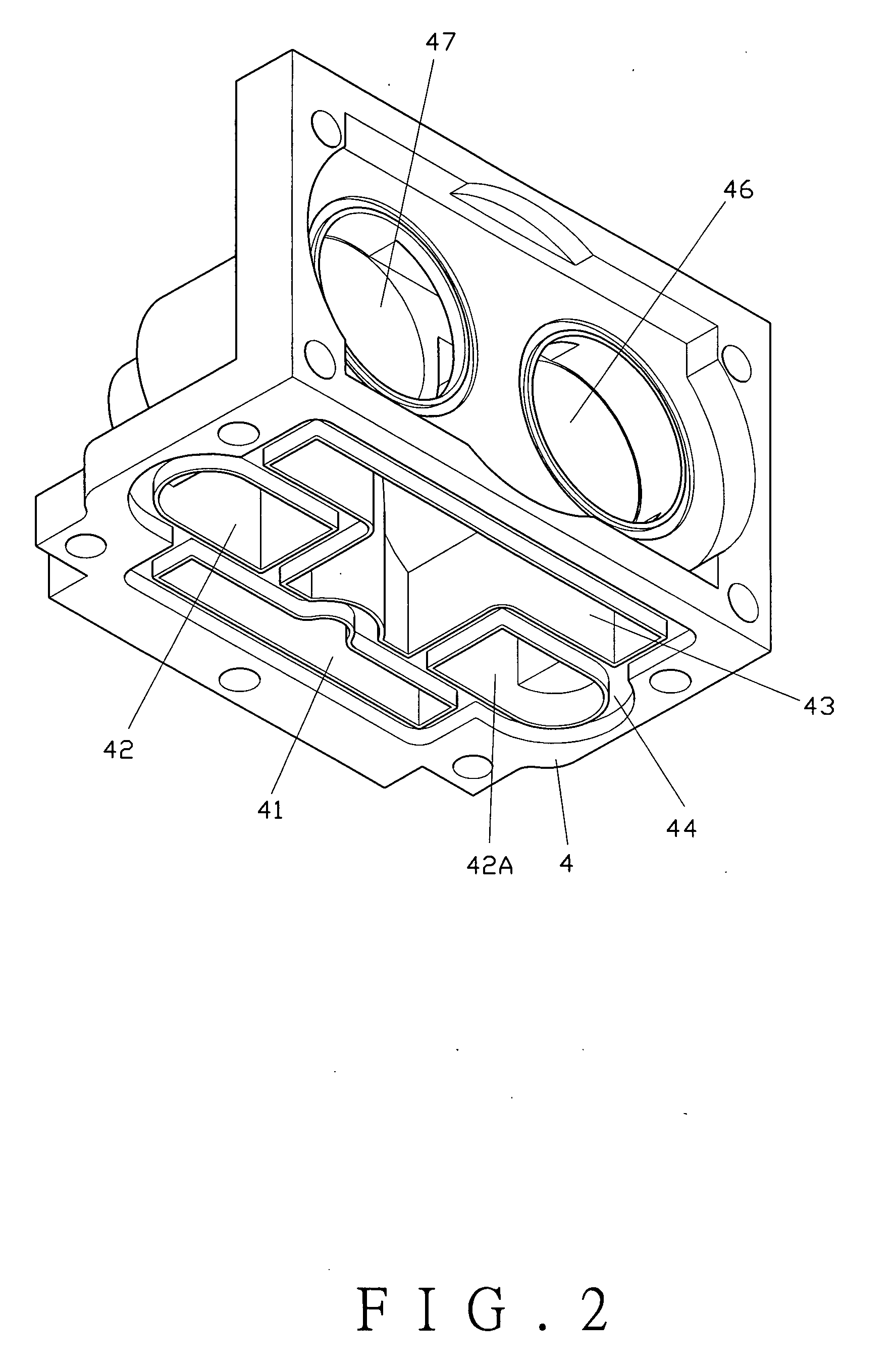
[0019] The air valve 4, as shown in FIG. 2, corresponds in shape to the valve seat 1 and comprises a first air chamber 41, a pair of secon...


PUM


Abstract

A control valve structure for an oxygen machine uses a motor to link a disc to spin, which activates a pair of valve rods to open and close in sequence through rotation of the motor to control air flow.

Description

BACKGROUND OF THE INVENTION [0001] 1. Field of the Invention [0002] This invention relates to a control valve structure for an oxygen machine, and more particularly to a pair of valve rods activated by a disc of a motor to control air passages. [0003] 2. Description of the Prior Art [0004] A conventional oxygen maker on the market uses an air compressor to suck air and to filter the air in the compressor before providing it to a user. The basic design is to suck air from outside into the compressor, and then filter the air to produce oxygen. [0005] U.S. Pat. No. 6,062,260 discloses a pair of electromagnetic valves of an air inlet control valve to control two pistons in the control valve to move in sequence so that air flows in and out in a circle status. [0006] However, should any of the electromagnetic valves is not functioning, the air flow in sequence is broken and air flow is out of control, thus oxygen can not be produced properly. SUMMARY OF THE INVENTION [0007] It is the prim...

Claims


Application Information

Patent Timeline
IPC IPC(8): F16K11/074F16K1/02
CPCF16K11/044F16K31/52416F16K31/047F16K11/165Y10T137/87708Y10T137/86405Y10T137/87209
Inventor HUANG, SHAO-SHIH
Owner HUANG SHAO SHIH
Why Eureka
Try Eureka