Subsea pressure compensation system

a pressure compensation system and submerged technology, applied in underwater equipment, sealing/packing, borehole/well accessories, etc., can solve problems such as overpressure of hydraulic fluid operation

Active Publication Date: 2006-10-19
VARCO I P INC
View PDF45 Cites 32 Cited by
  • Summary
  • Abstract
  • Description
  • Claims
  • Application Information

AI Technical Summary

Benefits of technology

[0014] Such pressure-compensated reservoirs which can effectively handle significantly large flows of fluid into and out of the reservoir;

Problems solved by technology

Reducing the applied pressure below the sea water pressure creates an overpressure of the operational hydraulic fluid.

Method used


Image

  • Subsea pressure compensation system
  • Subsea pressure compensation system
  • Subsea pressure compensation system

Examples


Embodiment Construction

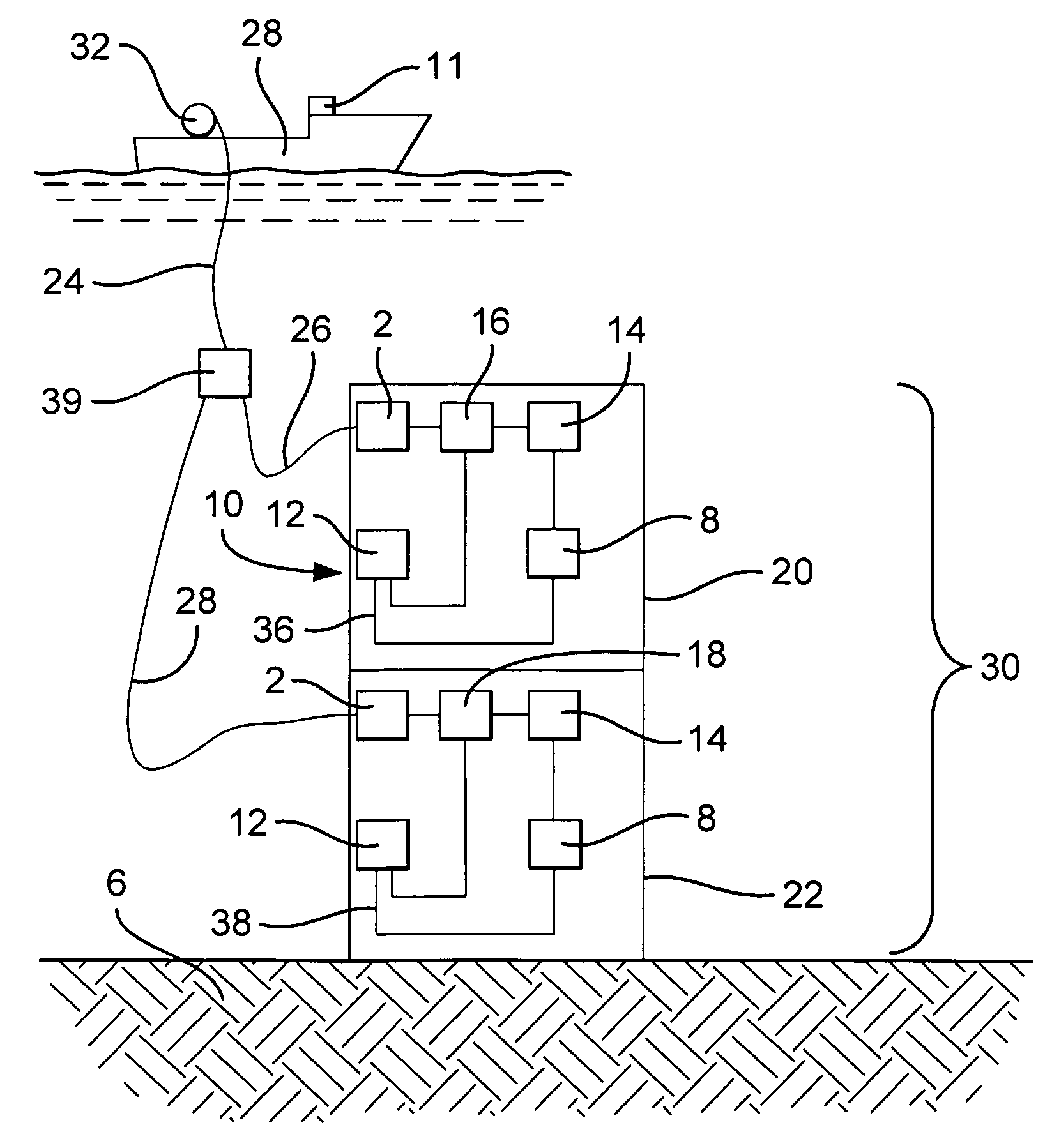
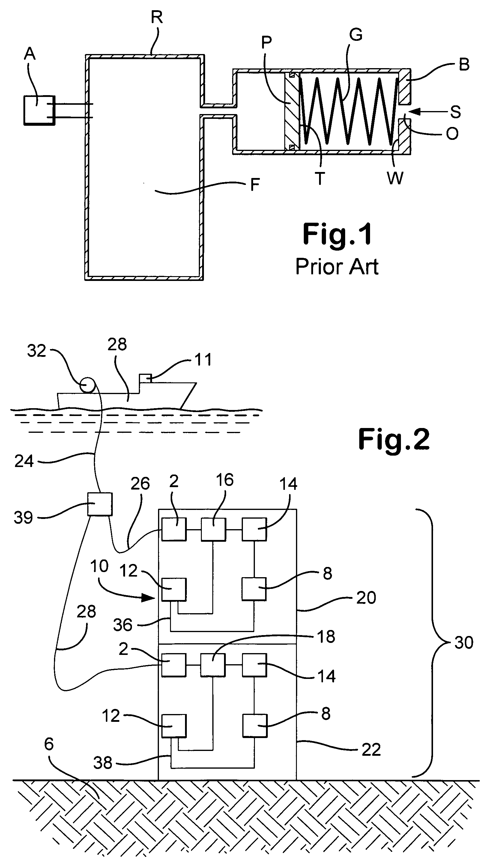
[0027]FIG. 2 shows a system 10 according to the present invention with a coiled tubing module 20 and a blowout preventer module 22, each including a pressure-compensated reservoir system 12 in fluid communication with one or a bank of accumulators 14, each of which is in fluid communication with an hydraulic power unit (16 or 18) of a subsea module 30 on a seafloor 6 in a closed-loop system. The hydraulic power unit 16 selectively operates a subsea coiled tubing system of the module 20 and the hydraulic power unit 18 selectively operates a subsea blowout preventer (“BOP”) system of the module 22. Fluid flows from the units 16, 18 to the accumulator(s) 14, to apparatus 8 (e.g., BOP; coil tubing apparatus) to be operated by the hydraulic power fluid, and then back to the reservoir system 12 in lines 36, 38 respectively. The system 12 has a reservoir charged at the surface to balance the pressure to be encountered at a depth at which the system will be used.

[0028] A power / communicatio...


PUM


Abstract

Systems and method for operating subsea devices and pressure compensated reservoir systems useful therewith which in certain aspects, include a chamber with a piston therein acted on an exposed side by water, e.g. sea water, to provide operational hydraulic fluid for operating a subsea device, with a piston rod having an end in a separate chamber acted on by a fluid to compensate for a pressure differential between the pressure of the water on one piston side and the pressure of the operational hydraulic fluid on the other piston side.

Description

BACKGROUND OF THE INVENTION[0001] 1. Field of the Invention [0002] The present invention is directed to underwater pressure compensation systems and, in certain particular aspects, to pressure compensation systems for closed-loop subsea hydraulic power systems. [0003] 2. Description of Related Art [0004] The prior art discloses a wide variety of pressure compensation systems for underwater apparatuses and systems. In many underwater systems such as closed-loop subsea hydraulic power systems, it is desirable to maintain sufficient pressure within the system (an “overpressure”) to prevent the ingress of sea water into the system. In certain closed-loop systems, the fluid used in the system is re-circulated; but when subsea systems are at a substantial depth below the water surface designs that would withstand the pressure at such depths require inordinate and excessively strong enclosures. To overcome this problem, “pressure-compensated” systems have been developed in which a subsea e...

Claims


Application Information

Patent Timeline
Patent Type & Authority Applications(United States)
IPC IPC(8): E21B29/12
CPCB63C11/52B63C11/00
Inventor MARTIN, DAVID W.
Owner VARCO I P INC
Why Eureka
Try Eureka