Adaptive predistortion linearized amplifier system employing selective sampling
a linearized amplifier and predistortion technology, applied in amplifiers, amplifier modifications to reduce noise influence, electrical equipment, etc., can solve problems such as corrupting the search process for optimal tuning parameters, unreliable differential log measurements, and undesirable gain of power amplifiers
- Summary
- Abstract
- Description
- Claims
- Application Information
AI Technical Summary
Benefits of technology
Problems solved by technology
Method used
Image
Examples
first embodiment
[0057] More specifically, referring to FIG. 7 an implementation of the selective sampling circuit with an analog input is shown. This implementation may be employed for circuit 122 of FIG. 1 and the input signals may be time aligned analog signals (m, θ, |x|) as described therein. The analog input signals are converted to discrete samples at analog sampling circuit 702 which outputs digital samples for time aligned triples (m, θ, |x|). These are provided to respective to temporary storage locations 704, 706, 708 which each store N samples. The N envelope samples are compared at envelope magnitude selection circuit 710 which selects the peak envelope sample from the N stored samples. Circuit 712 checks if the selected sample is an endpoint and if not the sample is selected as valid. If valid the sample number is output to magnitude and phase sample selection circuits 714, 716, respectively, which output the corresponding magnitude and phase samples. The circuit of FIG. 7 may be imple...
embodiment 1
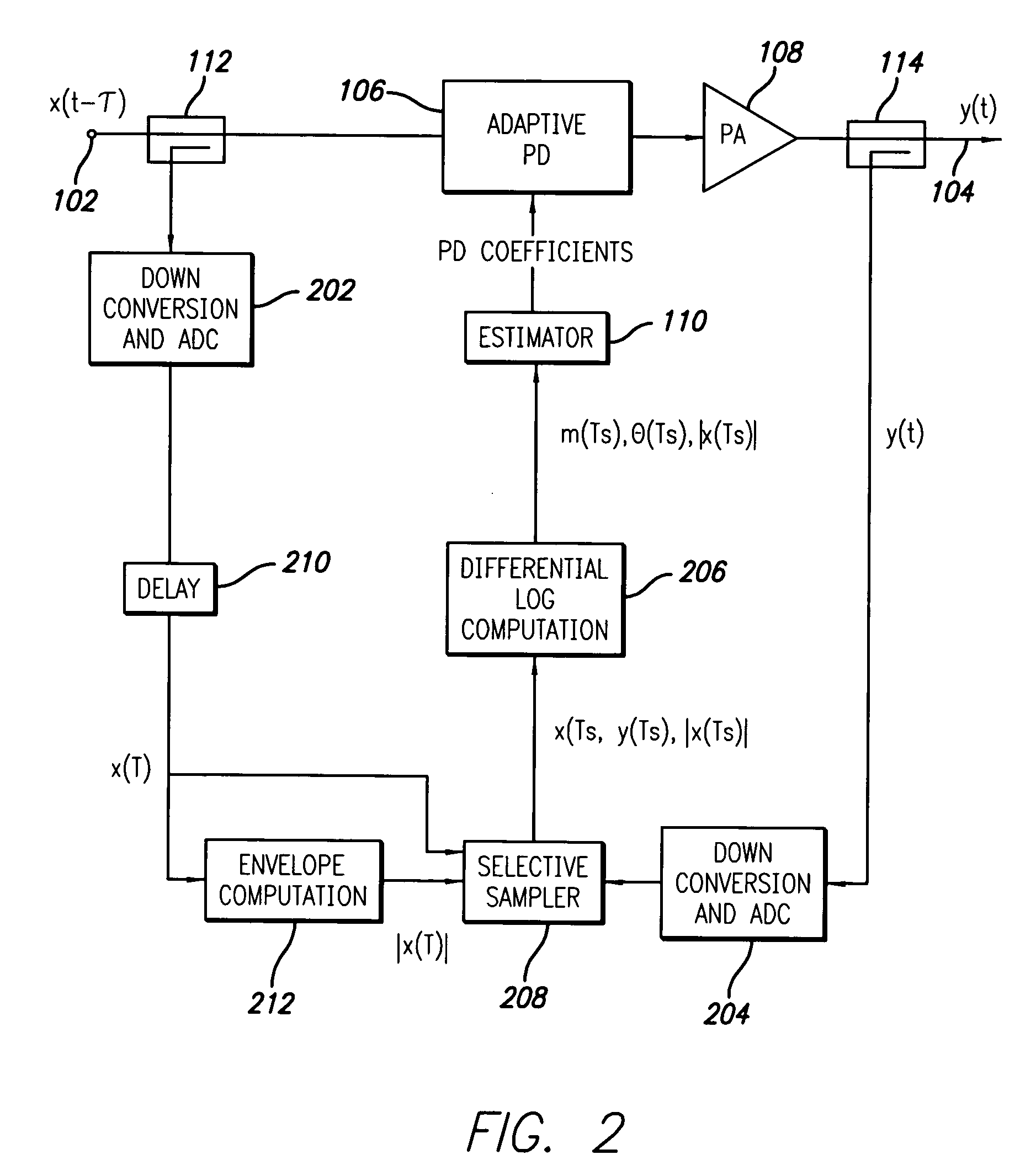
[0058] The implementation of the selective sampling circuit of FIG. 8 corresponds to embodiment 1 operating on digital samples, time aligned triples, as inputs. This implementation may be employed for the systems of FIGS. 2-6 and the circuit receives time aligned triples (m, θ, |x|) or (x, y, |x|) depending of the embodiment. The operation of the circuit corresponds to that of FIG. 7 after sampling circuit 702 and circuit blocks 804, 806, 808, 810, 812, 814 and 816 operate in the same manner as circuit blocks 704, 706, 708, 710, 712, 714 and 716 described above to select samples that are local peaks.
[0059] The second approach measures the ratio of the derivative of the input envelope and instantaneous input envelope: ∂xx,(Eq. 27)
where δ|x| is approximated, typically, by the difference between neighboring samples. The criteria for a valid sample becomes
∂|x|<η1·|x| and |x|>η2·E[|x|], (Eq. 28)
second embodiment
where η1 and η2 are thresholds (typical value for η2 is 0.3). The first threshold limits the input derivative of selected samples; the second threshold rejects samples obtained from low input levels. The optimal value of η1 depends, in part, on the technique used to measure of the derivative δ|x|. It requires normalization if the sampling rate is altered or if the estimates are obtained using a high pass filter. In general, a smaller value of η1 should be selected if the time-alignment between the input and output signals entering the differential log detector is imprecise or the memory within the power amplifier is not small. With the appropriate adjustments to the thresholds, η1 and η2, selective sampling can be based on the input power or log power instead of the input envelope. The block diagrams of two implementations of the selective sampler are shown in FIGS. 9 and 10.
[0060] More specifically, referring to FIG. 9 an implementation of the second embodiment of the selective sam...
PUM
 Abstract
Description
Claims
Application Information
 - R&D
- Intellectual Property
- Life Sciences
- Materials
- Tech Scout
- Unparalleled Data Quality
- Higher Quality Content
- 60% Fewer Hallucinations
Browse by: Latest US Patents, China's latest patents, Technical Efficacy Thesaurus, Application Domain, Technology Topic, Popular Technical Reports.
© 2025 PatSnap. All rights reserved.Legal|Privacy policy|Modern Slavery Act Transparency Statement|Sitemap|About US| Contact US: help@patsnap.com


