Tire information transmitter and tire information acquisiton system using the transmitter

Inactive Publication Date: 2006-10-19
YOKOHAMA RUBBER CO LTD
View PDF3 Cites 11 Cited by
  • Summary
  • Abstract
  • Description
  • Claims
  • Application Information

AI Technical Summary

Benefits of technology

[0039] Accordingly, the tire information transmitter and the tire information acquisition system of the present invention allow the control unit to irreversibly shift, once the pressure signal level exceeds the threshold value, from the comparing mode in which the pressure signal level is compared with the threshold value level continually after the start of supplying the driving power, to the transmission mode in which the transmitting unit transmits the pressure signal at a predetermined time interval. As a result, the transmitting unit can transmit only significant and effective information of the ambient information in the tire cavity region that is obtained after the tire is inflated with air, rather than transmit less significant information, for example, the pressure information obtained with a tire in an initial stage, which is not inflated with air.
[0040] Further, the tire information transmitter and the tire information acquisition system of the present invention allow the transmitting unit to transmit an operation sig

Problems solved by technology

This contributes to a longer battery life.
However, in the conventional tire information transmitters, input of radio wave from outside is necessary in order to activate the transmitter, and thereby a receiving circuit is required, causing the system configuration to be complicated.
This in turn increases system cost.
In addition, for the conventional tire information transmitters, input of radio wave from outside is necessary in order to trigger the transmission of ambient information, thereby requiring additional work and time.
Further, in the conventional tire information transmitters, it is necessary to provide a switching device for switching in order to trigger the transmission of ambient information, which requires additional work and time.
In conventional tire information transmitters that are provided with a lead terminal, the transmission is triggered by applying a predetermined voltage to the lead terminal, thereby also requiring additional work and time.
In addition, as described

Method used


Image

  • Tire information transmitter and tire information acquisiton system using the transmitter
  • Tire information transmitter and tire information acquisiton system using the transmitter
  • Tire information transmitter and tire information acquisiton system using the transmitter

Examples


Example

[0049] Hereinafter, a tire information transmitter and a tire information acquisition system of the present invention will be described in detail based on a preferred embodiment shown in the accompanying drawings.

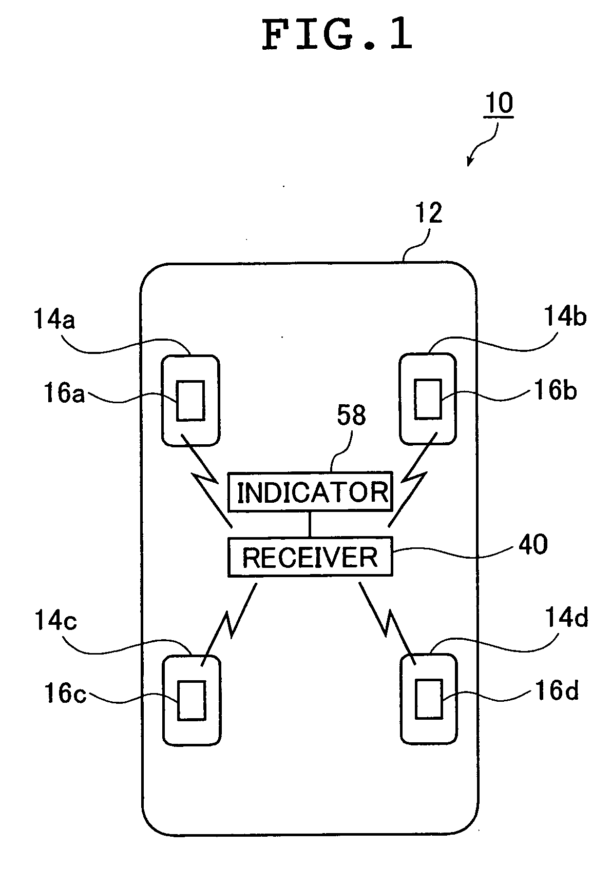
[0050]FIG. 1 is a schematic view of a tire information acquisition system using the tire information transmitter according to an embodiment of the present invention.

[0051] As shown in FIG. 1, wheel assemblies 14a-14f each having a tire and a wheel, are mounted to respective wheel mounting positions of a vehicle 12. A tire information acquisition system 10 of this embodiment is, for example, provided on a passenger car.

[0052] As shown in FIG. 1, the tire information acquisition system 10 of this embodiment includes tire information transmitters 16a-16d (hereinafter referred to as “tire transmitter(s)”) mounted to respective wheel assemblies 14a-14f, a receiver 40 for receiving a transmission signal from the respective tire transmitters 16a-16d, and an indicator 58 for ind...


PUM


Abstract

A tire information transmitter measures tire inflation pressure in a tire cavity region and wirelessly transmits it outside the tire cavity region. A control unit of the transmitter controls the transmitting of the measured pressure and compares the level of the pressure signal with a threshold value continually after a supply of driving power is started. The transmitter has a comparing mode in which the operation signal is transmitted at a first time interval, and a transmitting mode in which the pressure signal is transmitted at a second time interval, which is shorter than the first time interval. Further, the control unit irreversibly shifts from the comparing mode to the transmitting mode, once the level of the pressure signal exceeds the threshold value as a result of the comparing.

Description

BACKGROUND OF THE INVENTION [0001] 1. Field of the Invention [0002] The present invention relates to tire information transmitters which are mounted to vehicles having wheel assemblies, such as trucks, buses, passenger cars and motor-bikes, and transmit ambient information in a tire cavity region, such as, a tire inflation pressure and a tire temperature, and the present invention also relates to tire information acquisition systems using the tire information transmitter. Priority is claimed from JP 2005-37874, the disclosure of which is incorporated herein by reference thereto. [0003] 2. Description of the Prior Art [0004] Nowadays there have been proposed tire monitoring systems used in vehicles such as trucks, buses, passenger cars and motor-bikes, that are provided with wheel assemblies each including a wheel and a tire, for constantly monitoring a pressure (hereinafter alternatively referred to as the tire inflation pressure) in the tire cavity region surrounded by a tire inter...

Claims


Application Information

Patent Timeline
IPC IPC(8): B60C23/00
CPCB60C23/0484B60C23/0408
Inventor NAKATANI, KOJIEBINUMA, TOSHIMITSUNIHEI, HIDEKI
Owner YOKOHAMA RUBBER CO LTD
Why Eureka
Try Eureka