
Bidirectional motor stall protection circuit

Inactive Publication Date: 2006-10-19
LEAR CORP
View PDF20 Cites 34 Cited by
  • Summary
  • Abstract
  • Description
  • Claims
  • Application Information

AI Technical Summary

Benefits of technology

[0010] According to another aspect of the present invention, a method of protecting an electric motor against damage caused by stalling is provided. The method includes sensing the level of current supplied to the motor. The sensed level of current provided to the motor is then compared to a threshold value. An interrupt signal is sent to a latch circuit if the sensed level of current exceeds the threshold value. The flow of current to the motor is interrupted when the interrupt signal is received from the latch circuit to protect the motor from damage.

Problems solved by technology

When the motor drives the seat to either maximum position, the motor may stall if the switch controlling the motor is continued to be actuated after the seat reaches the maximum travel position.
Stalling the electric motor may cause damage to the motor.
PTC devices tend to degrade with time.
Circuit breakers are subject to hysteresis effects that may cause intermittent seat operation.

Method used


Image

  • Bidirectional motor stall protection circuit
  • Bidirectional motor stall protection circuit
  • Bidirectional motor stall protection circuit

Examples


Embodiment Construction

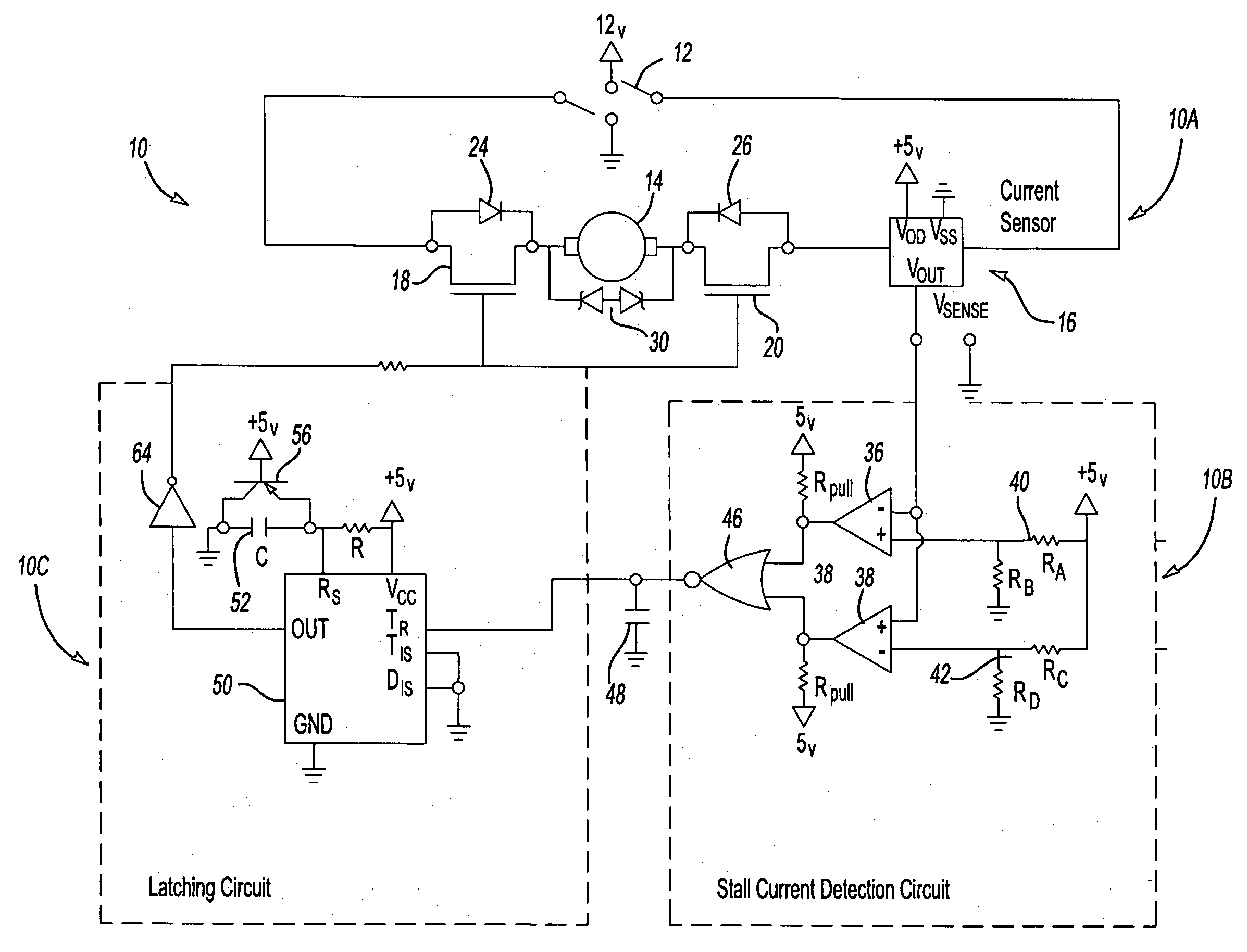
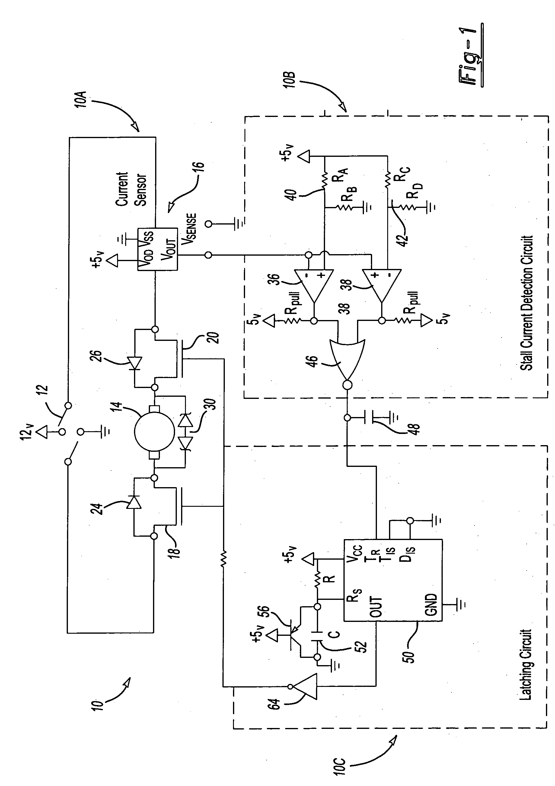
[0017] Referring to FIG. 1, one embodiment of a stall current protection circuit is generally referred to by reference numeral 10. The stall current protection circuit 10 includes a motor drive circuit portion 10A, a stall current detection circuit portion 10B and latching circuit portion 10C.

[0018] The motor drive circuit portion 10A includes a half bridge switch 12 that has forward, reverse, and off positions. The half bridge switch 12 is a bipolar power-driver output. A motor 14 is controlled by half bridge switch 12 that switches the motor 14 for operation in a forward mode, reverse mode, and turns the motor off. A Hall effect current sensor 16 is a low current Hall effect current sensor that may sense current on PCB traces, and the like. The current sensor 16 senses the level of current provided to the motor 14 and produces a voltage output that is proportional to the sensed current.

[0019] A pair of forward N channel MOSFETs 18 and 20 are provided on opposite sides of the mot...


PUM


Abstract

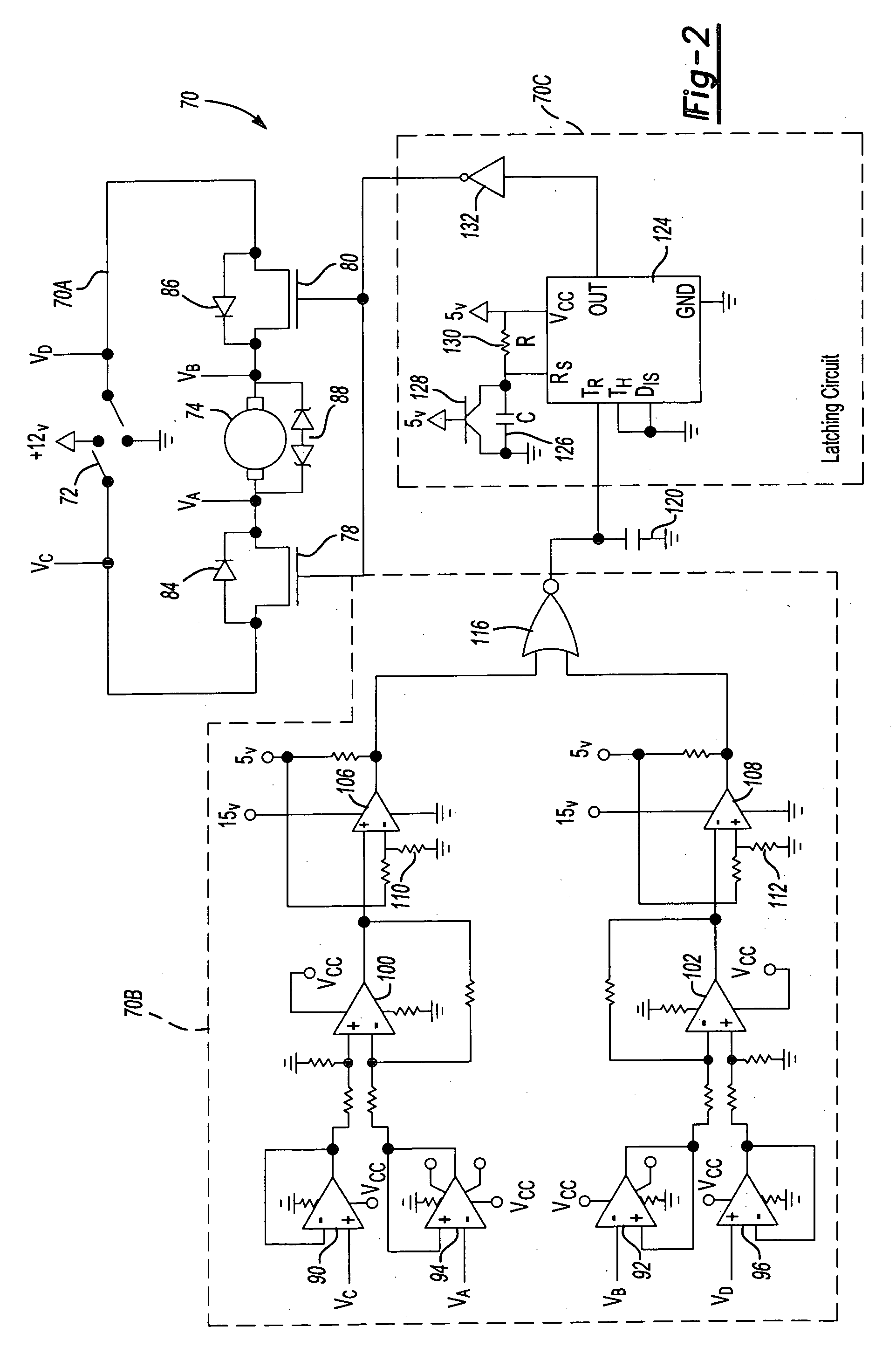
A stall protection circuit is provided for bidirectional motor operation that is controlled by a half bridge switch that has forward, reverse and off positions. A method of protecting a motor is also disclosed. A Hall effect current sensor may be provided in a stall current protection circuit that engages a latching circuit. The latching circuit is operative to interrupt current flowing to the motor by disabling MOSFETs on opposite sides of the motor. Alternatively, FET voltage from drain to source may be used to measure the current supplied to the motor that is used to engage the latching circuit.

Description

BACKGROUND OF THE INVENTION [0001] 1. Field of the Invention [0002] The present invention relates to electrical circuits for protecting an electric motor from damage caused by stalling the motor. [0003] 2. Background Art [0004] Small, low current electric motors are used in a myriad of applications in which a reversible drive is required. Examples of some applications include vehicle seat positioning systems, seat recliners, window regulator drives, mirror positioning systems, and the like. For example, a reversible motor may be used in a vehicle seat to control the fore-and-aft positioning of the vehicle seat in a track. The motor is used to adjust the seat forwardly or rearwardly to accommodate a seat occupant. Seats move within tracks between a maximum forward position and a maximum rearward position that is determined by stops defining the length of the track. When the motor drives the seat to either maximum position, the motor may stall if the switch controlling the motor is co...

Claims


Application Information

Patent Timeline
IPC IPC(8): H02H7/08
CPCH02H7/0851
Inventor MAUE, H. WINSTONNATHAN, JOHN F.PAJOR, MICHAELNOORMAN, MICHAELBALLARD, JOHN R.ANDERSON, JERREMYKUCHER, PAUL
Owner LEAR CORP
Learn More