Treatment plant

a technology of treatment plant and treatment chamber, which is applied in the direction of mixer, cleaning process and apparatus, fouling prevention, etc., can solve the problems of product loss, time-consuming and cost-intensive, and complicating the cleaning between individual charges, so as to reduce the complexity of cleaning and reduce the time of cleaning, the effect of reducing downtim

Inactive Publication Date: 2006-10-19
EKATO RUHR & MISCHTECHN
View PDF91 Cites 8 Cited by
  • Summary
  • Abstract
  • Description
  • Claims
  • Application Information

AI Technical Summary

Benefits of technology

[0009] As the medium is prevented from adhering to at least most of those regions of the treatment plant according to the invention that come into contact with the fluid medium, product loss can be effectively reduced, when the treatment plant is emptied, and cleaning jobs in particular can be executed rapidly and more efficiently between the respective charges. Such a treatment plant thus meets the high standards demanded of purity and reproducibility of the purity. Therefore, such a treatment plant is especially appropriate for pharmaceutical and cosmetic products and for the preparation of foodstuffs. As a result of fewer residues, the strain on waste water is also diminished. The medium-repellent property is realized in particular on the vertical and inclined surfaces in the container of the treatment plant to repel the medium during emptying and drain it in accordance with the force of gravity. As a result, the medium can be discharged almost entirely together with the product mass in the container interior. Cleaning jobs and the complexity of cleaning are hereby also simplified because the surfaces and components of the treatment plant in contact with the medium are already substantially pre-cleaned.
[0014] An essential feature of the present invention is the construction of a treatment plant in which essentially all regions that may come in contact with the medium, in particular in a container of such a treatment plant, have the property to repel the respective medium to enable a substantially full emptying of the treatment plant and in particular the container in the absence of any significant medium loss. At the same time, the complexity of cleaning is reduced as far as time expended as well as costs are concerned so as to realize and attain an effective cleaning of such a treatment plant to meet highest standards in connection with the reproducibility of the purity. This is especially of significant advantage when producing pharmaceutical and cosmetic products. As a consequence of the reduced cleaning times, it is also possible to reduce downtimes of such a treatment plant so that the treatment planet can be operated and utilized more efficiently.

Problems solved by technology

Residues adhering in the treatment plant during emptying cause product loss and complicate a cleaning between the individual charges.
This is time-consuming and cost-intensive.

Method used


Image

  • Treatment plant
  • Treatment plant

Examples


Embodiment Construction

[0016] The depicted embodiment is to be understood as illustrative of the invention and not as limiting in any way. It should also be understood that the drawings are not necessarily to scale and that the embodiments are sometimes illustrated by graphic symbols, phantom lines, diagrammatic representations and fragmentary views. In certain instances, details which are not necessary for an understanding of the present invention or which render other details difficult to perceive may have been omitted.

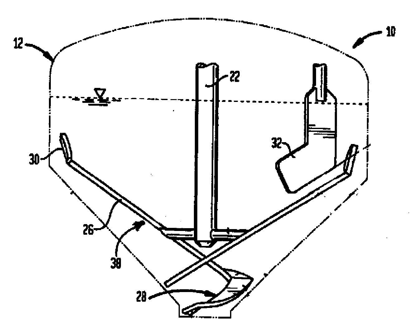
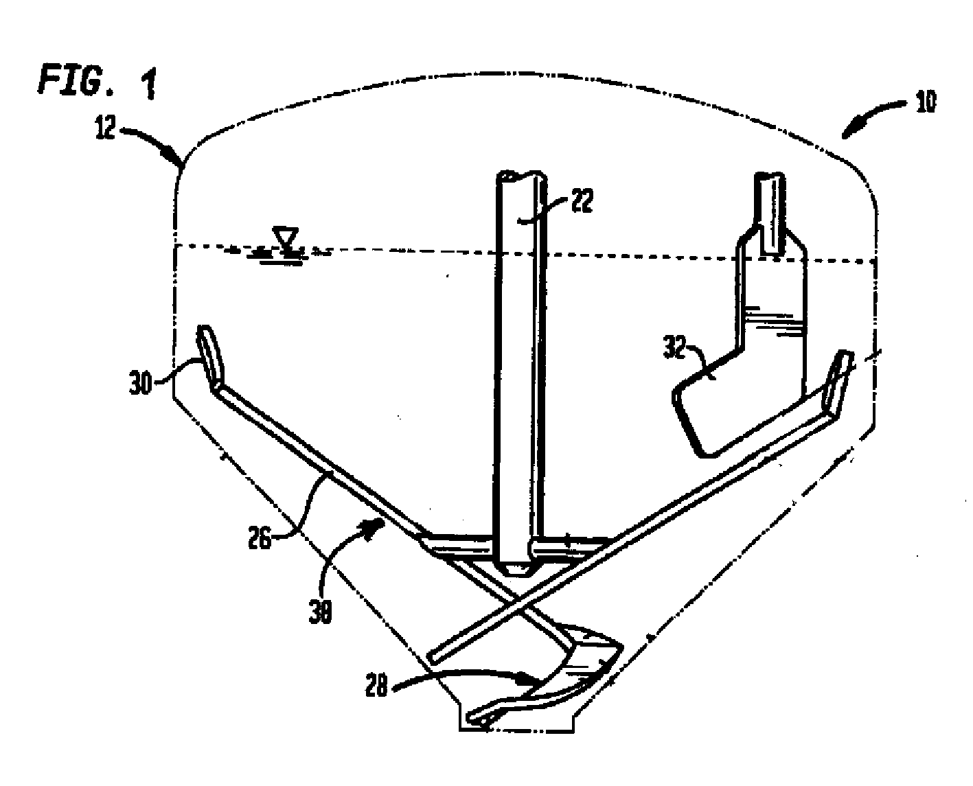
[0017] Turning now to FIG. 1, there is shown a simplified schematic view of a treatment plant according to the present invention, generally designated by reference numeral 10. The construction of the treatment plant 10 is shown here by way of example only, and the present invention should not be limited to the details shown here. The treatment plant 10 includes a container 12 whose outline is shown here only by way of a dash-dot line, and an agitator, generally designated by reference nu...


PUM


Abstract

A treatment plant in particular for a liquid medium of average to high viscosity, for example for production of pharmaceutical and cosmetic products includes a container in which an agitator, built-in structures, heat exchange elements, baffles or the like may be arranged. To reduce medium loss and to effectively clean such a treatment plant, any region or component of the treatment plant that comes into contact with the fluid medium is provided with a medium-repellent coating.

Description

CROSS-REFERENCES TO RELATED APPLICATIONS [0001] This application claims the priority of German Patent Application, Serial No. 10 2005 017 327.6-23, filed Apr. 14, 2005, pursuant to 35 U.S.C. 119(a)-(d), the content(s) of which is / are incorporated herein by reference. BACKGROUND OF THE INVENTION [0002] The present invention relates to a treatment plant for fluids of average to high viscosity but also for treatment of media of low viscosity. [0003] Nothing in the following discussion of the state of the art is to be construed as an admission of prior art. [0004] As a consequence of the high viscosity or a pronounced yield point, these media tend to adhere during emptying to the contact areas, such as the container wall, to built-in structures, such as baffles or heat exchange elements, to an agitator with agitator shaft and agitator blades. Examples of such media include adhesives or sealing materials (hot melts, silicone rubber, etc.), dyes and paints, cosmetics or pharmaceutical pro...

Claims


Application Information

Patent Timeline
Patent Type & Authority Applications(United States)
IPC IPC(8): B01F7/20B01F27/906
CPCB01F7/00041B08B17/06B01F15/00844B01F27/0531B01F35/512
Inventor HIMMELSBACH, WERNER
Owner EKATO RUHR & MISCHTECHN
Why Eureka
Try Eureka