Delivery Pump

a technology for moving pumps and pumps, applied in the direction of machines/engines, stators, liquid fuel engines, etc., can solve the problems of affecting the cleaning of the pump, affecting the cleaning effect of the pump, and affecting the reliability of the pump, etc., to achieve rapid product changes, accurate adjustment, and easy cleaning

Inactive Publication Date: 2010-05-06
KSB AG
View PDF11 Cites 8 Cited by
  • Summary
  • Abstract
  • Description
  • Claims
  • Application Information

AI Technical Summary

Benefits of technology

[0009]A further object of the invention is to provide a pump unit having a delivery rate which is variable, pulsation-free and accurately adjustable over a wide range for delivering differing media having different properties.
[0010]An additional object of the invention is to provide a delivery pump which which can be cleaned easily for rapid product changes.

Problems solved by technology

Such positive-displacement pumps have the disadvantage of the lack of reliability due to friction between the components to be sealed off, moved in relation to one another, and their pulsating delivery stream.
A resulting outlay in terms of maintenance and the costs for wearing parts and for exchanging these are detrimental to rapid research and development work and appreciably disrupt a production process.
The disadvantage of this canned motor design is the multiplicity of gaps which, because of the complex flow routing between the pump and canned motor, seriously impede the cleaning of the pump.
Since part of the delivery fluid flows permanently through the motor and its gap space, a high introduction of heat into the delivery fluid occurs due to the frictional heat of the rolling bearings and to the heat loss from the canned motor.
If this pump were operating under part load, an inadmissibly high introduction of heat would take place very quickly.
This would result not only in damage to the fluid, but also in a failure of the pump as a result of cavitation or dry running.

Method used


Image

  • Delivery Pump
  • Delivery Pump
  • Delivery Pump

Examples


Embodiment Construction

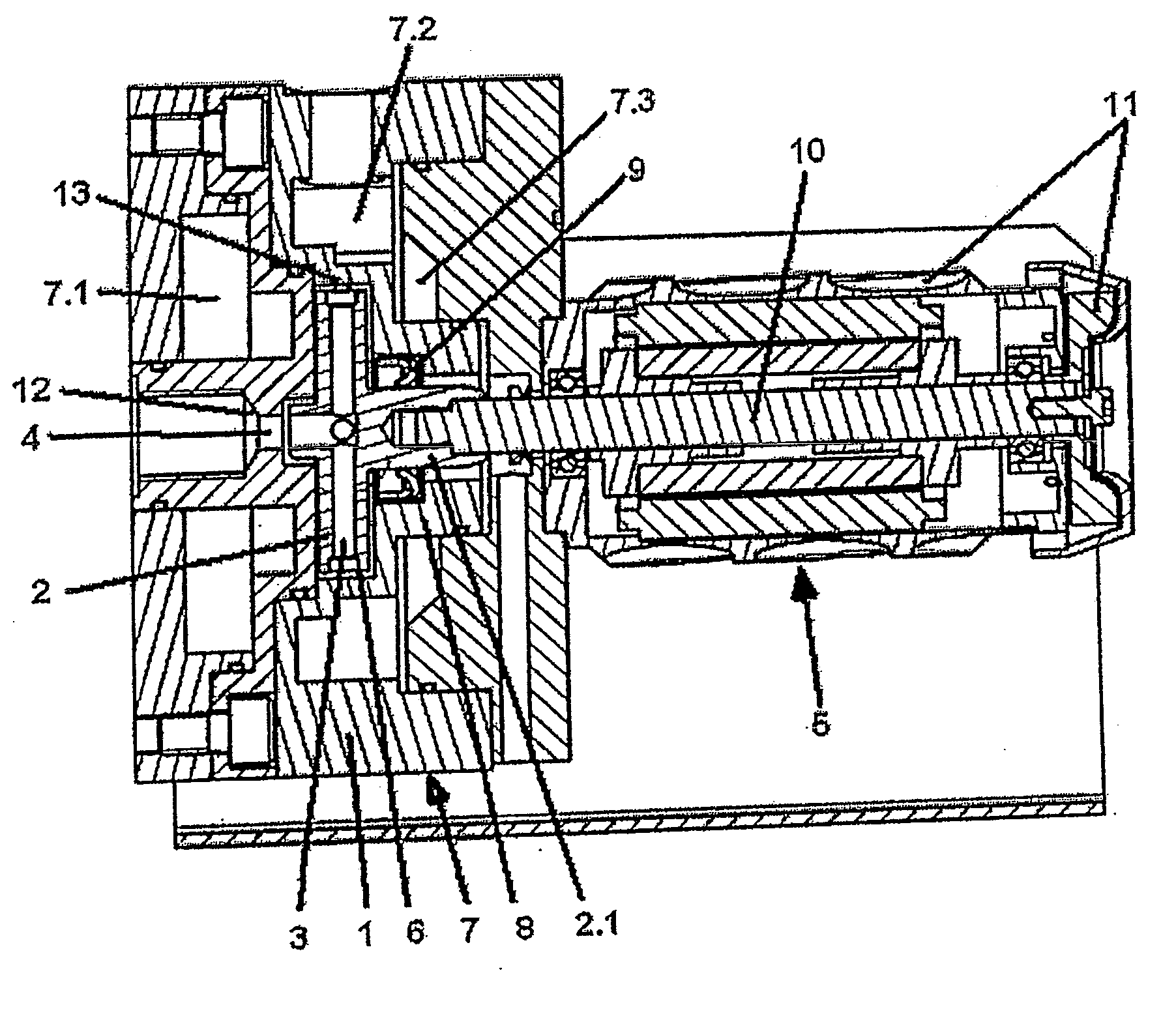
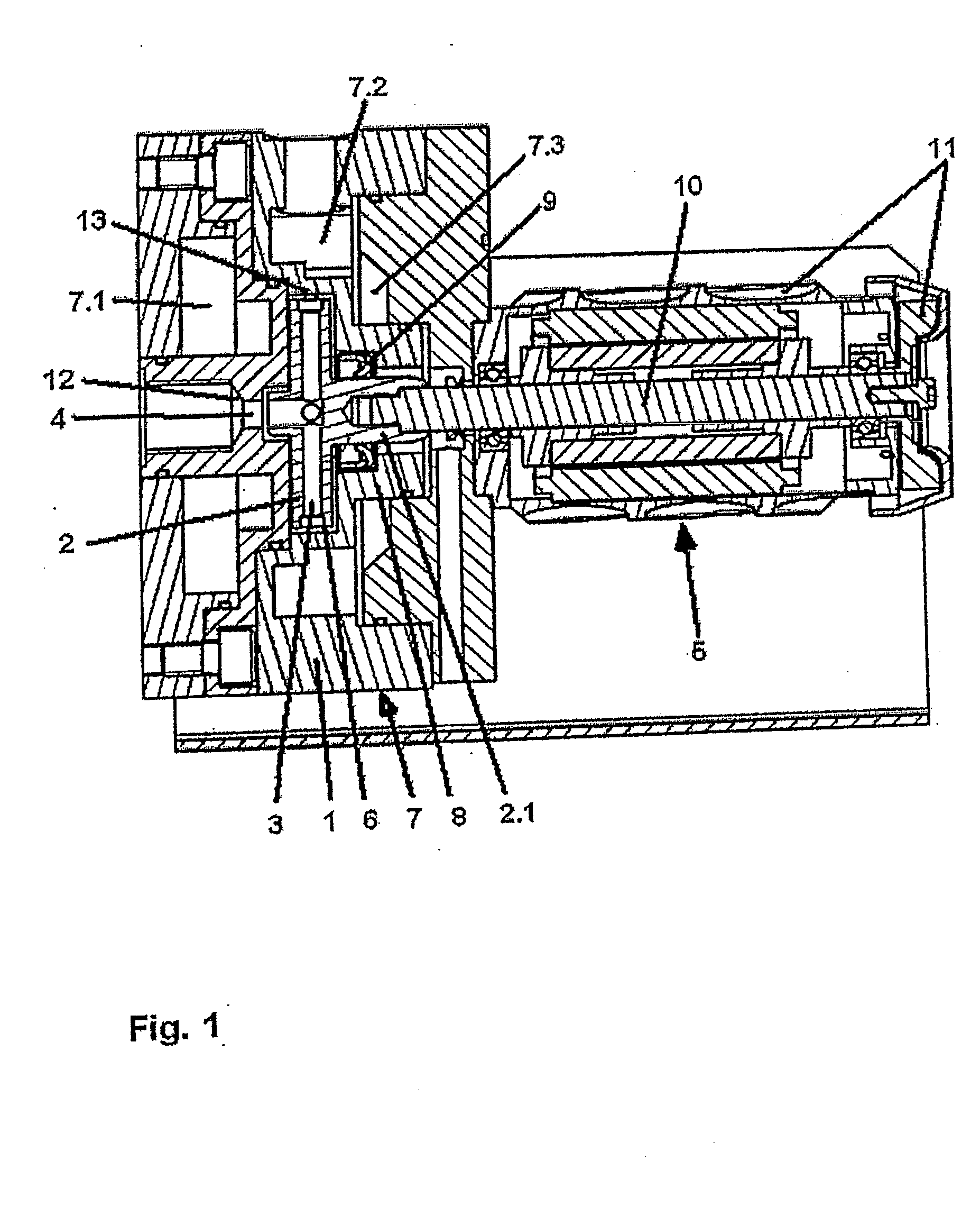
[0026]FIG. 1 illustrates a delivery pump having a single-stage pump construction. A radial impeller 2 of centrifugal type of construction is arranged rotatably in the pump casing 1. The radial impeller 2 has delivery ducts 3 and receives the flow centrally through a pump inlet 4. The radial impeller 2 is connected in a force-transmitting manner to a variable-speed drive 5 and has an outside diameter DLA which may amount to up to 70 mm. The radial impeller rotates in an impeller chamber 6, the inside diameter DLRI of which is designed to be only a maximum of 4% larger than the outside diameter DLA, of the radial impeller 2.

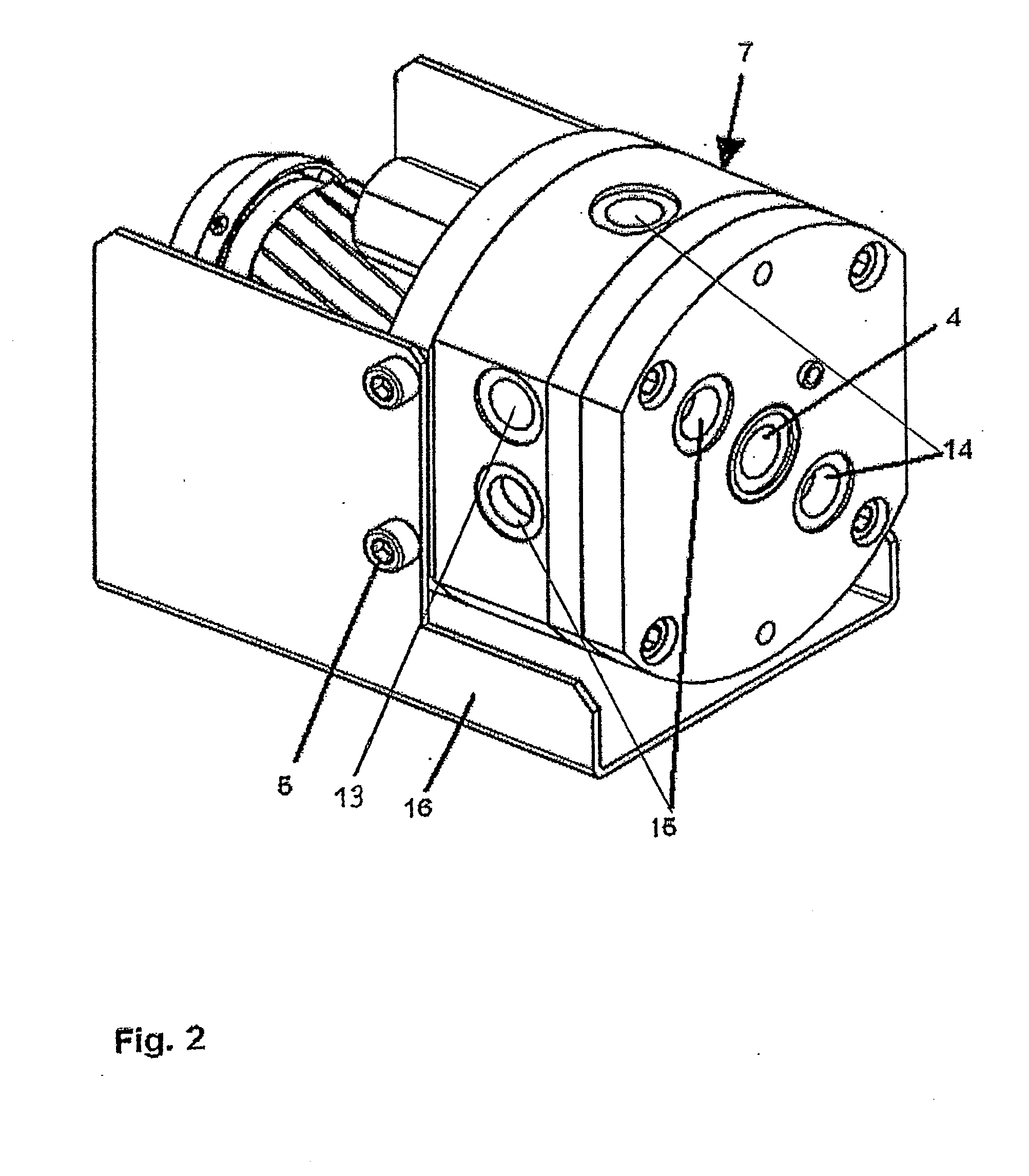
[0027]The pump casing 1 is provided with a thermal control device 7 which in this illustrative embodiment is integrated in the pump casing. Other forms of construction are also possible. Cooling spaces 7.1 to 7.3 surround the impeller chamber 6 and also a seal casing 8 contiguous to the pump casing 1. Within the seal casing 8 is arranged, as a type of shaft seal, a...


PUM


Abstract

A delivery pump for conveying a liquid between a pump inlet and a pump outlet, the pump being constructed as a single-stage centrifugal pump with a radial impeller (2) having a centrifugal construction arranged rotatably in an impeller chamber (6) of a pump casing (1); the impeller being connected to a variable-speed drive motor (5) variable in speed into the five-digit range of revolutions per minute, and the impeller receiving liquid flow centrally, and being provided with radially-extending delivery ducts (3), and at outside impeller diameters of up to 55 mm developing rotational speed-dependent delivery heads of up to 300 m. For use in a process engineering system, the delivery pump is designed for nominal operation in the form of continuous centrifugal pump part-load operation with delivery rates in the range of 0 ml/min to 7000 ml/min; the nominal operation is characterized by a centrifugal pump part-load-specific rotational speed nqTL≧0.05≦10 (l/min), and the impeller chamber (6) comprises one or more pump outlet ducts (13) located on the circumference at acute angles to or tangentially to the outside diameter of the radial impeller.

Description

CROSS REFERENCE TO RELATED APPLICATIONS[0001]This application is a continuation of international patent application no. PCT / EP2008 / 002767, filed Apr. 8, 2008 designating the United States of America and published in German on Nov. 6, 2008 as WO 2008 / 131846 A1, the entire disclosure of which is incorporated herein by reference. Priority is claimed based on Federal Republic of Germany patent application no. DE 10 2007 020 218.2, filed Apr. 28, 2007.BACKGROUND OF THE INVENTION[0002]The invention relates to a delivery pump with a variable-speed drive, the delivery pump being designed as a single-stage centrifugal pump with a radial impeller (2) of centrifugal type of construction, arranged rotatably in an impeller chamber of a pump casing (1), for delivering a fluid between a pump inlet (4) and a pump outlet (13), the radial impeller (2) being connected to a drive motor variable in speed into the five-digit range of revolutions per minute, the radial impeller (2) receiving the flow cent...

Claims


Application Information

Patent Timeline
Patent Type & Authority Applications(United States)
IPC IPC(8): F04D29/58F04D29/42F04D13/02
CPCF04D29/225F04D15/0066F04D29/588
Inventor BINDER, AXELJAEGER, CHRISTOPHKELLER, CHRISTOPH
Owner KSB AG
Why Eureka
Try Eureka