Hydraulic Damper With Compensation Chamber

a technology of damper and compensation chamber, which is applied in the direction of shock absorber, vibration damper, spring/damper, etc., can solve the problems of affecting car safety, comfort, noise, etc., and achieve the effects of reducing production specific losses, increasing dissipating energy, and reducing the cost of large-scale production

Inactive Publication Date: 2009-12-31
BWI CO LTD SA
View PDF6 Cites 9 Cited by
  • Summary
  • Abstract
  • Description
  • Claims
  • Application Information

AI Technical Summary

Benefits of technology

[0009]An object of the present invention is to provide a compression valve module for existing suspension dampers with a compensation chamber, which might be simply employed as an add-on device, affecting neither tuning options nor performance of rebound and compression valve assemblies of their base valve assemblies in normal operating range of the piston velocities but beneficially increasing an amount of dissipated energy during extremely fast compression strokes. Such a compression valve module should comprise only a few simple components, as compared to known designs, and share comparable working characteristic within a large range of dimensional tolerances of these components therefore minimizing the production specific losses, and consequently decreasing the costs of large scale production.
[0011]The compression valve module forms a normally open, quick-closing, throttling valve which operation is independent of the piston position and dependent only on the piston velocity. The valve module comprises only a few additional components which provide easy tuning of the engagement velocities and force gains. As the annular area between the disc and the inner surface of the damper tube enables a substantially unrestricted flow of working fluid in normal operating range of piston velocities, the acceptable dimensional tolerance of the disc is largely increased. The compression valve module can be formed as a separate sub-assembly and installed in a hydraulic damper when required without modification of the other components of the damper.
[0012]The flat floating disc enables improved valve dynamics due to its low mass which beneficially affects a shorter valve response, low impact forces during triggering, and insensitivity on inertial forces caused by the unsprung mass acceleration. The valve module wear is decreased due to low impact loading and wide flat contact surfaces. The term “floating” means that without the force of the spring, the disc would be free to displace along and rotate around the piston rod axis.
[0013]On the other hand the spring prevents fluctuations in the working fluid, and ensures that the flow of working fluid through the compression valve module components, both in its open and closed positions, shall be substantially laminar with no adverse effect on the operation of the base valve assembly elements.

Problems solved by technology

Although dampers featuring low compression forces with degressive characteristics are desired to improve passengers comfort, during severe road and / or drive conditions they also often lead to maximally admissible wheel-knuckle displacements in the direction of damper compression leading to a suspension closure or jounce bumper engagement, which in turn may affect the car safety, comfort, durability and noise issues.

Method used


Image

  • Hydraulic Damper With Compensation Chamber
  • Hydraulic Damper With Compensation Chamber
  • Hydraulic Damper With Compensation Chamber

Examples


first embodiment

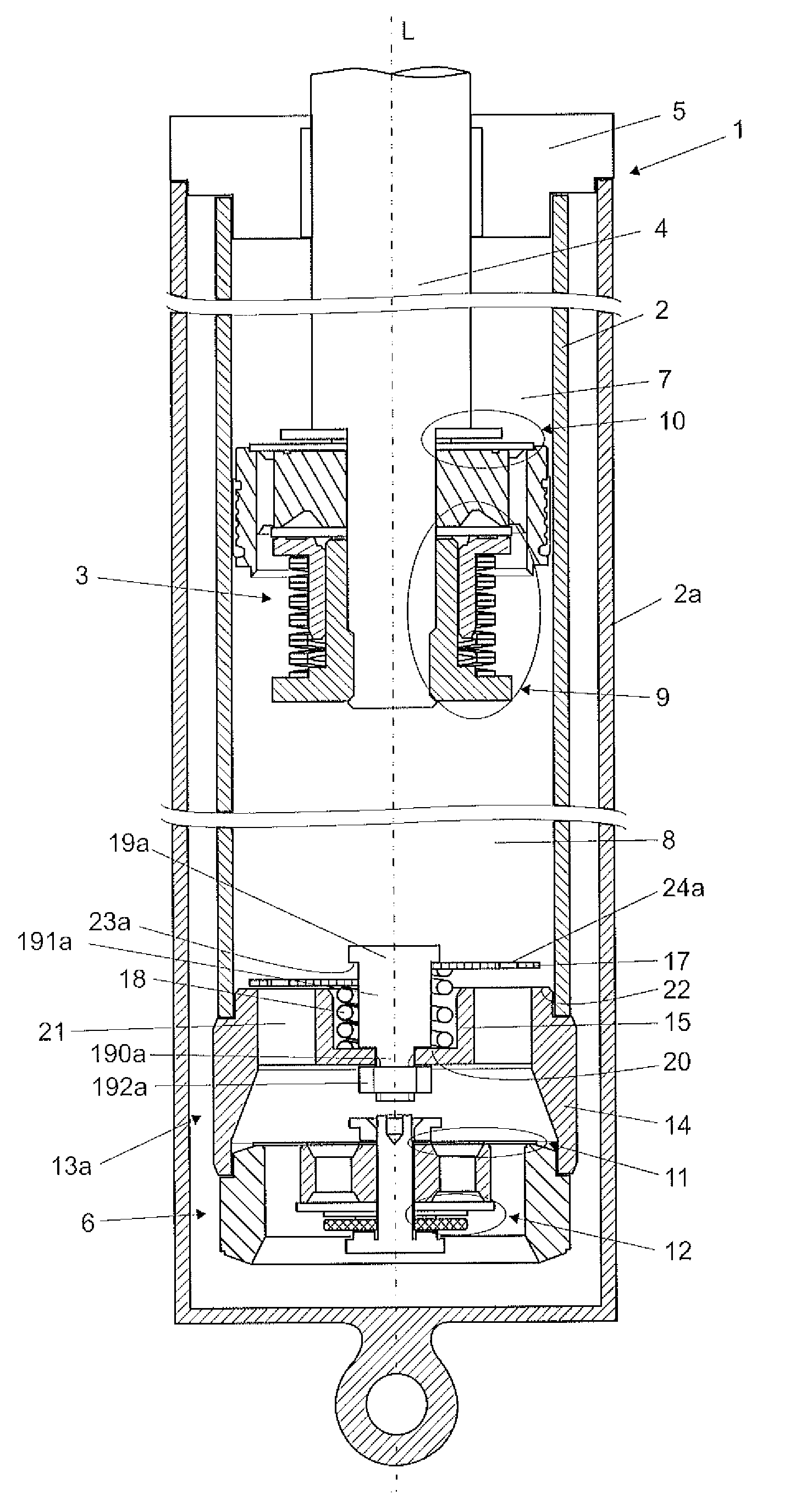
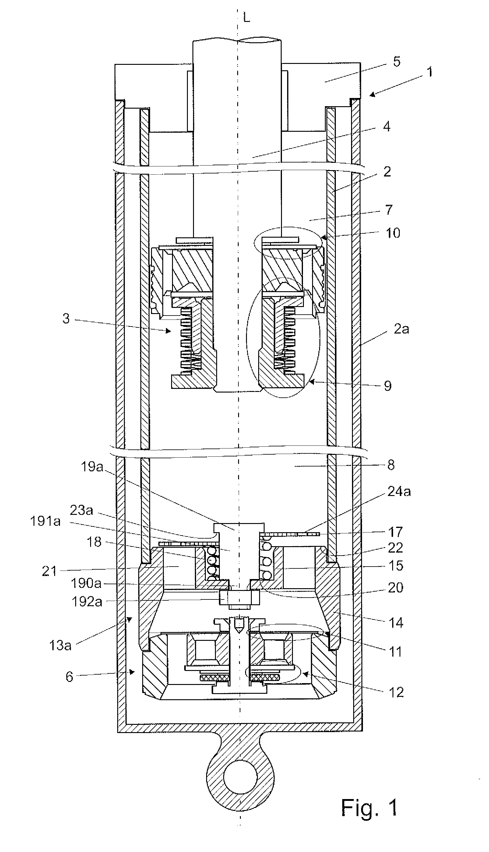
[0033]The compression valve module 13a according to the invention is shown in FIG. 1 in closed (first) and opened (second) position respectively on the left and on the right side of the damper longitudinal axis L. The compression valve module 13a comprises an outer tubular member 14 with an inner cylindrical or tubular member 15 connected thereto via a number of radially extending bridge members 16 (cf. FIGS. 2, 5, 6 and 7). The outer tubular member 14, the inner cylindrical member 15 and the bridge members 16 are preferably made as one element in a sintering process using sintered carbides or in a cold press forming process. The outer and inner tubular members 14, 15 are substantially coaxial along the longitudinal axis L. A fluid flow passage 21 is defined between the outer 14 and the inner tubular member 15. The flange of the outer tubular member 14 defines an abutment surface 22 on the side remote from the base valve assembly 6.

[0034]Further the valve module 13a comprises a thin...

third embodiment

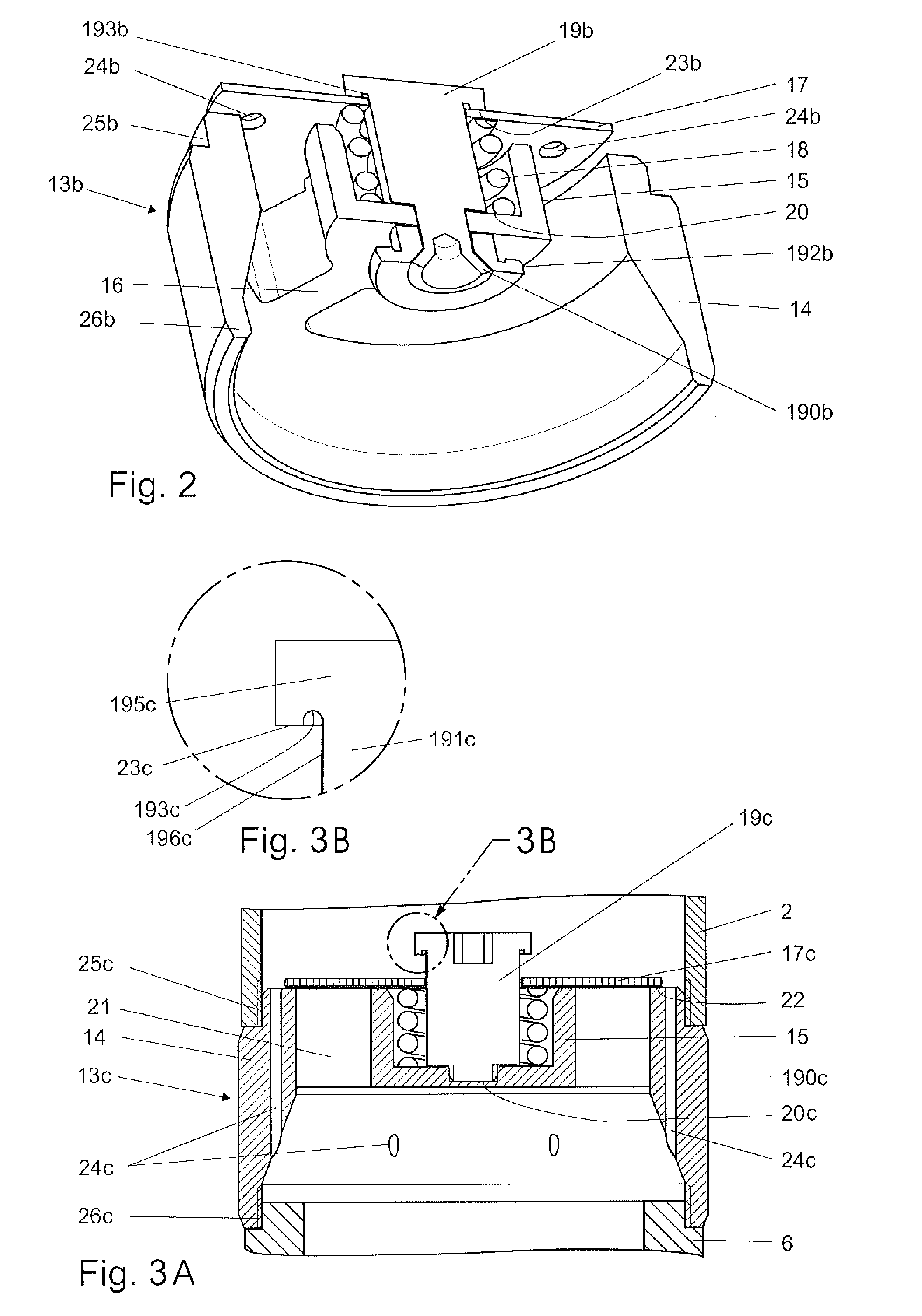
[0044]FIG. 3a shows a compression valve module 13c. In this embodiment the base surface 20c of the inner cylindrical member 15c is provided with a centrally situated, bottom closed internally threaded opening into which the fixing portion 190c of the retaining bolt 19c in a form of a screw is screwed.

[0045]An enlarged detail in FIG. 3b shows the annular recessed groove 193c formed in the bottom surface 23c of the head 195c of the retaining bolt 19c which directly adjoins the outer surface 196c of the bolt 19c shaft 191c. The groove 193c improves the dimensional tolerance between the retaining bolt 19c and the closing disc 17. In bolts formed according to typical known processes, a fillet is present in the corner formed by the bolt head and the bolt shaft. As a consequence of using such a bolt in cooperation with the disc provided with central opening and tightly fitted to the bolt shaft, the disc 17 might become wedged to the bolt in the open position, and consequently its sliding m...

fourth embodiment

[0048]Reference is now made to FIG. 4 and FIG. 5 depicting a compression valve module according to the present invention. Retaining means have in this embodiment a form of a cup-shaped cage member 19d, which is secured to the outer tubular member 14. The cage member 19d comprises an annular part 195d and a number of shaped arms 191d extending away from the annular part. The shaped arms 191d are attached to the outer tubular member 14. The disc open position is defined by an abutment surface 23d of the annular part 195d which is spaced from the abutment surface 22 in the axial direction L. In this embodiment the inner tubular member 15, having cylindrical shape, is partially closed at one end (the end adjacent the base valve assembly 6) with a base surface in a form of an inturned lip 20, and the spring 18 is compressed between the inturned lip 20 and the disc 17. Moreover the fluid flow passages 21 are defined between the outer 14 and the inner 15 tubular members, as well as through...


PUM


Abstract

The invention relates to a hydraulic damper, in particular for the suspension system of a motor vehicle, comprising a tube filled with working fluid; a piston assembly slidably positioned inside the tube; a fluid compensation chamber located outside of the tube, and a base valve assembly at the end of the tube for controlling the flow of working fluid between the tube and the compensation chamber. A compression valve module added between the piston assembly and the base valve assembly allows the damping to increase during extremely fast compression strokes without modification of the other damper components, affecting neither tuning options nor performance in a normal operating range of piston velocities.

Description

TECHNICAL FIELD[0001]The present invention relates to a hydraulic damper with a compensation chamber (usually configured or referred to as a twin-tube damper), and in particular to a hydraulic damper for the suspension system of a motor vehicle.BACKGROUND OF THE INVENTION[0002]Suspension dampers of this kind generally comprise a tube filled with working fluid, inside of which a slidable piston assembly is placed. The piston assembly is attached to a piston rod led outside the damper through a piston rod guide, and comprises a piston with rebound and compression valve assemblies, which control the flow of working fluid passing through the piston assembly during the rebound and the compression stroke of the damper. A base valve assembly located at the end of the tube of the damper opposite to the piston rod and provided with separate rebound and compression valve assemblies controls the flow of working fluid passing in and out of a compensation chamber, commonly formed between the inn...

Claims


Application Information

Patent Timeline
Patent Type & Authority Applications(United States)
IPC IPC(8): F16F9/34
CPCF16F9/3487F16F9/516F16F9/512
Inventor WIDLA, WALDEMARSLUSARCZYK, PAWELWRZESINSKI, JAKUBANDRES, KRYSTIAN MARCIN
Owner BWI CO LTD SA
Why Eureka
Try Eureka