Loudspeaker with low-frequency oscillation

a low-frequency oscillation and loudspeaker technology, applied in the field of loudspeakers, can solve the problems of difficult to produce low-frequency sound, and achieve the effect of enhancing the response

Inactive Publication Date: 2006-10-19
HUANG JUI CHEN
View PDF2 Cites 13 Cited by
  • Summary
  • Abstract
  • Description
  • Claims
  • Application Information

AI Technical Summary

Benefits of technology

[0008] A primary object of the invention to provide a loudspeaker with low-frequency oscillation that has a longer oscillation element under the condition

Problems solved by technology

Thus, it is difficult to produce low-frequency sound.
Thus, it is diffic

Method used


Image

  • Loudspeaker with low-frequency oscillation
  • Loudspeaker with low-frequency oscillation
  • Loudspeaker with low-frequency oscillation

Examples


first embodiment

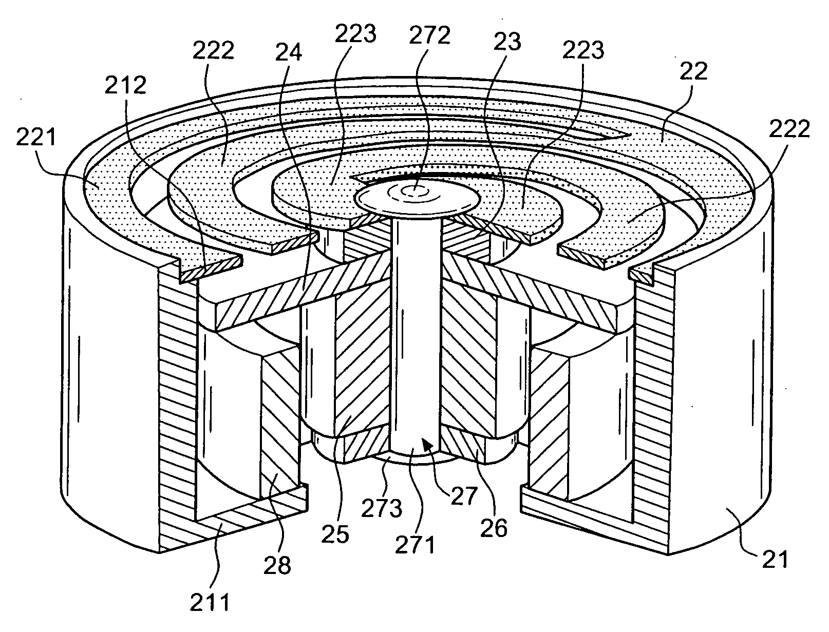
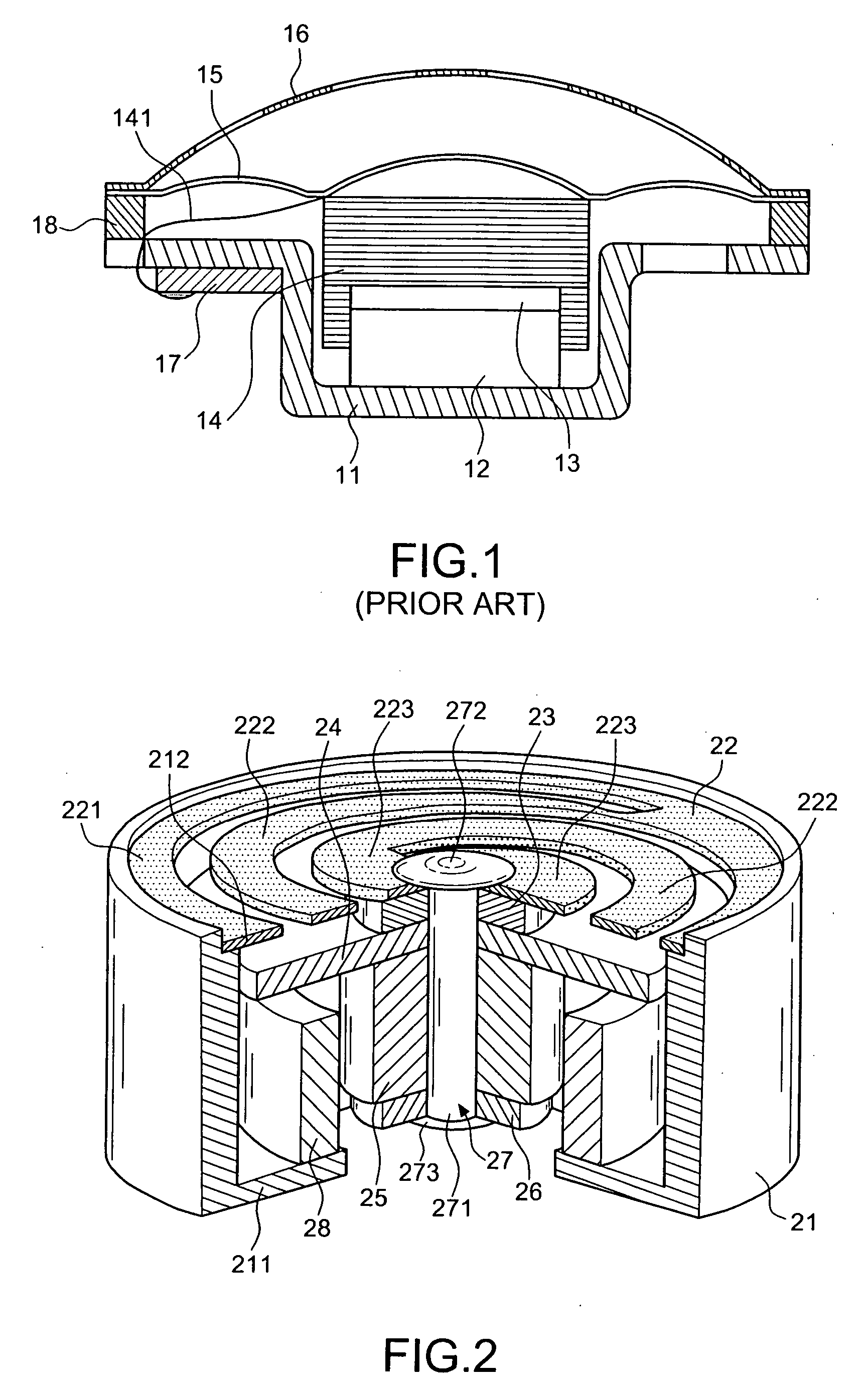
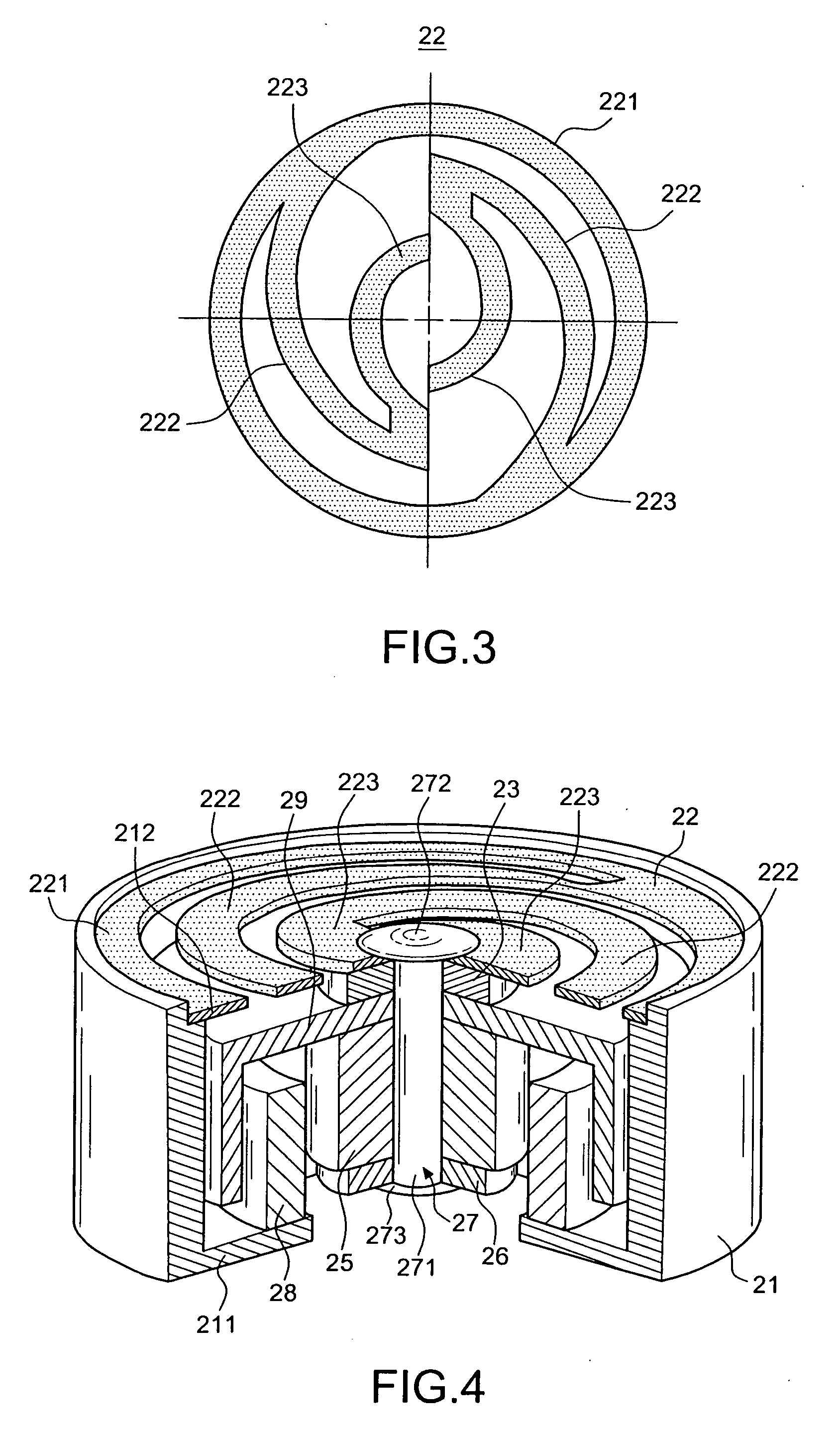
[0021] Referring to FIGS. 2 and 3, a loudspeaker with low-frequency oscillation in accordance with the invention includes a housing 21 with a ring portion 211 extending inwardly from the bottom of the housing 21 and a grooved support portion 212 extending inwardly from the top thereof; and a reed element 22 with an external ring 221 and two vibration arms 222 symmetrically extending from the internal side of the external ring 221 to the internal side of the loudspeaker in a bent manner. Each of the vibration arms 222 includes a free end 223 extending to the center of the reed element 22, as shown in FIG. 3.

[0022] An upper ring 23, a sound element 24, a magnetic ring 25, and a lower ring 26 are disposed one after another under the free end 223 of the reed element 22 within the housing 21. The sound element 24 includes a central through hole. A shaft body 27 includes a pin 271 combining the central holes of the upper ring 23, the sound element 24, the magnetic ring 25, and the lower r...

second embodiment

[0026]FIG. 7 shows a perspective view of the invention in accordance with FIG. 4. As shown in FIG. 7, the coil 28 can be firstly secured to the housing 21. Thereafter, the reed element 22, the upper ring 23, the sound element 29, the magnetic ring 25, and the lower ring 26 of the oscillatable sound assembly are mounted on the shaft body 27 to create a composite unit 30 which is then placed into the housing 21. Thus, the assembly in accordance with FIG. 4 is formed. Meanwhile, the upper portion 213 of the housing 21 can be made of elastic material like silicon while the ring portion 211 of the lower portion of the housing 21 can be made of hard material. Then, the upper and the lower portion of the housing 21 are combined together. In this way, when the reed element 22 vibrates, a vibrating movement can be imparted to the upper portion 213 of the housing 21, thereby increasing the vibrating and massaging effect of the whole body. Furthermore, a protection cover 31 is disposed on the ...


PUM


Abstract

A loudspeaker with low-frequency oscillation, comprising: a housing (21) with a ring portion (211) extending inwardly from the bottom thereof; and a reed element (22) having a top end attached to an oscillatable sound assembly, the reed element (22) further having an external ring (221) and two vibration arms (222) symmetrically extending from the internal side of the external ring (221) to the internal side of the loudspeaker in a bent manner, each of the vibration arms (222) having a free end (223) extending to the center of the reed element (22), the oscillatable sound assembly including either a magnetic ring (25) or a coil (28) disposed within the housing (21), the ring portion (211) being attached to either another coil corresponding to the magnetic ring (25) or another magnetic ring corresponding to the coil (28), whereby, when the coil (28) is fed with electric current, a magnetic force is created to impart an up and down vibration to the oscillatable sound assembly, thereby enhancing the effect of the low-frequency sound field as well as the resonance effect.

Description

BACKGROUND OF THE INVENTION [0001] 1. Field of the Invention [0002] The invention relates to a loudspeaker, and more particularly, to a minitype loudspeaker with low-frequency oscillation. [0003] 2. Description of the Related Art [0004] A conventional minitype loudspeaker, as disclosed by a Japanese company CITIZEN, in TW 515219 as well as TW 515218 (U.S. Pat. No. 6,690,809 B2 and U.S. Pat. No. 6,400,825 B1) includes a diaphragm that produces sound by means of vibration. The circumference of the diaphragm is secured to a top housing. The longer the diameter of the diaphragm is, the lower sound is produced. The short the diameter of the diaphragm is, the higher sound is produced. However, the diameter of the diaphragm of the earphone loudspeaker is dependent on the dimensions of the housing of the earphone. Thus, it is difficult to produce low-frequency sound. [0005] As shown in FIG. 1, an earphone loudspeaker disclosed in TW 504099 includes a base 11 with a groove formed at the cent...

Claims


Application Information

Patent Timeline
IPC IPC(8): H04R11/02
CPCH04R1/1016H04R1/22H04R2400/07H04R2400/03H04R11/02H04R9/02H04R9/04
Inventor HUANG, JUI-CHEN
Owner HUANG JUI CHEN
Why Eureka
Try Eureka