Storm water retention chambers

Active Publication Date: 2006-10-19
ADVANCED DRAINAGE SYST
View PDF22 Cites 27 Cited by
  • Summary
  • Abstract
  • Description
  • Claims
  • Application Information

AI Technical Summary

Benefits of technology

[0013] It is further contemplated that the length of the connection chambers may, in one advantageous embodiment, be provided shorter than a length of the standard molded chamber structures that it is connected with. The connection chambers are provided with a plurality of upstanding ribs, providing increased strength to the structure.
[0014] The arch-shaped cut out provided at a bottom portion in the sidewall of the connection chambers is sized to receive an arch-shaped row connector, which may be formed as a miniature molded chamber structure. The row connector may or may not be provided with end wall sections. In either event, once the arch-shaped cut out is removed by the user, an end of the row connector may be inserted therein providing a continuous connection from one row to the next. The row connector is arch-shaped, including the plurality of upstanding ribs and therefore provides a very sturdy connection from row to row. In addition, as the ends of the row connector are positioned in relatively close tolerance

Problems solved by technology

For example, concrete tanks are extremely heavy requiring heavy construction equipment to put them in place.
In leaching fields and stormwater collection systems, the gravel used in constructing them is difficult to work with and expensive.
While the chambers themselves are relatively large to accommodate a large volume of fluid, the pipes interconnecting the different rows of chambers restrict the free flow of fluid throughout the field.
This is undesirable because the fluid is not uniformly distributed throughout the field but instead is maintained generally at the e

Method used


Image

  • Storm water retention chambers
  • Storm water retention chambers
  • Storm water retention chambers

Examples


Embodiment Construction

[0027] Referring now to the drawings, wherein like reference numerals designate corresponding structure throughout the views.

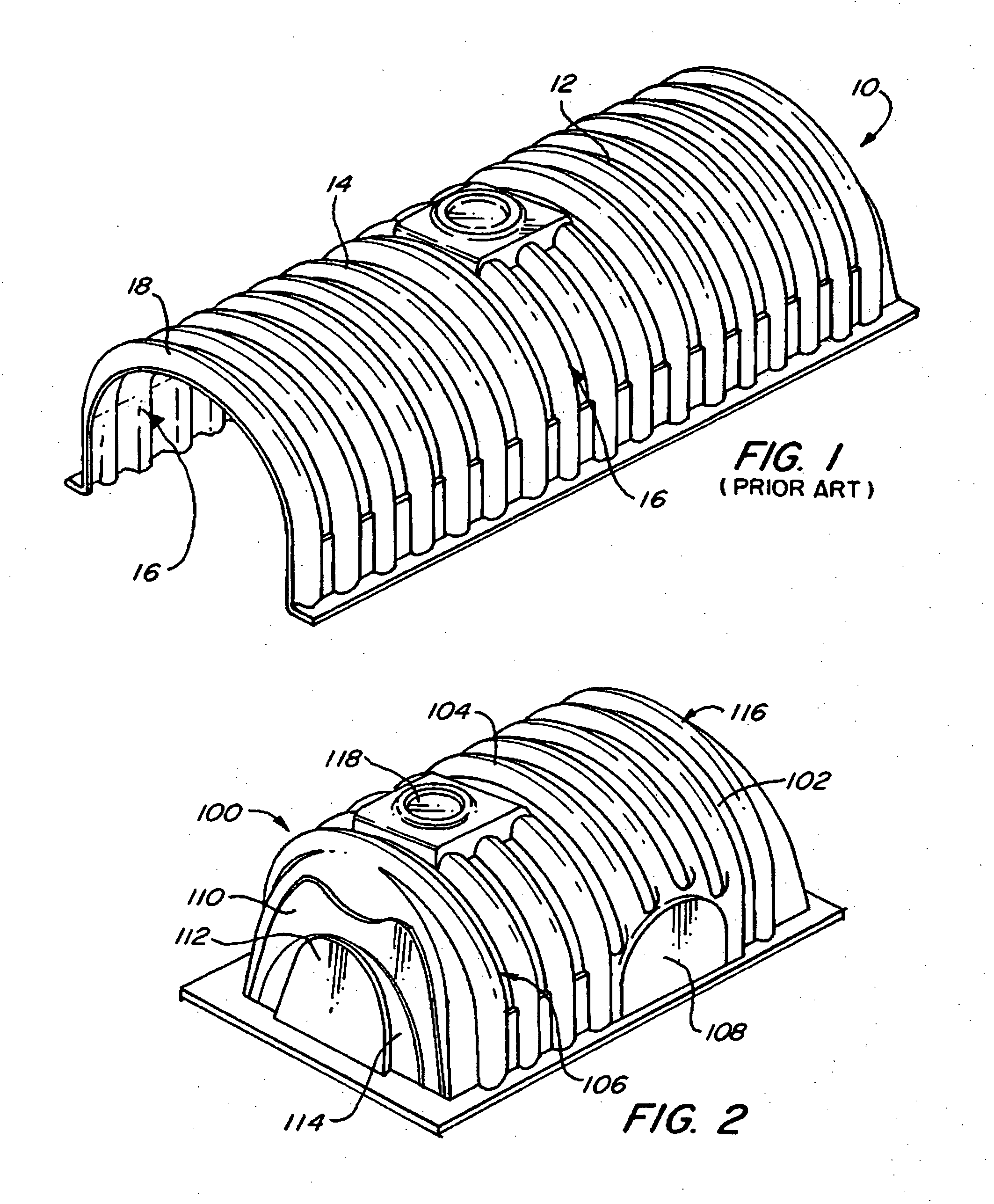
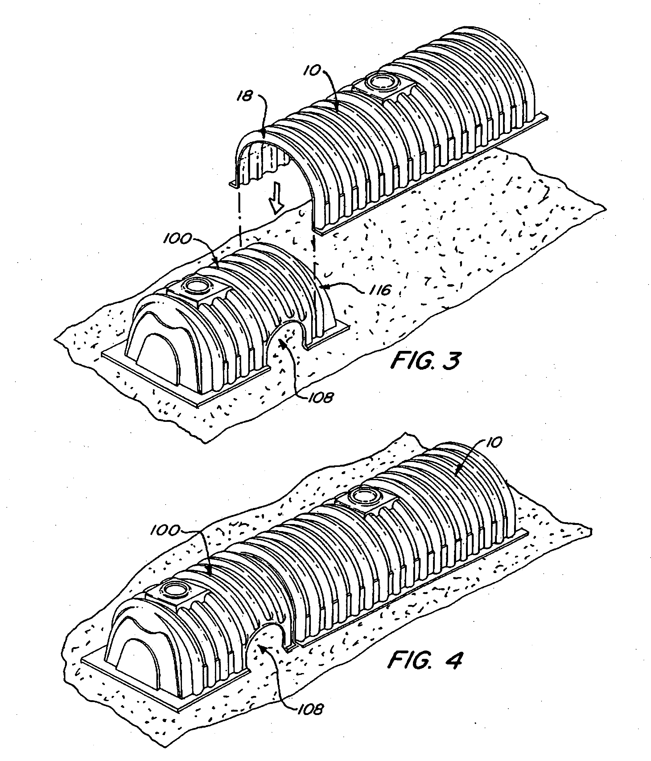
[0028]FIG. 1 is an illustration of a molded chamber structure 10 according to the prior art. As can be seen from the illustration, the molded chamber structure 10 generally comprises an arch-shaped body portion 12 that includes a plurality of upstanding ribs 14. The body portion 12 is provided with an open bottom such that side walls 16 essentially rest on the surface of the bed of materials. The molded chamber structure 10 may or may not be provided with an end wall.

[0029] Molded chamber structure 10 is provided with a starting rib 18, which is designed to mate with end rib 116 on connection chamber 100 (FIG. 2). Molded chamber structure 10 typically comprises, for example, a vacuum-molded polyethylene chamber. However, other polymer materials may be used, including injection molded polypropylene.

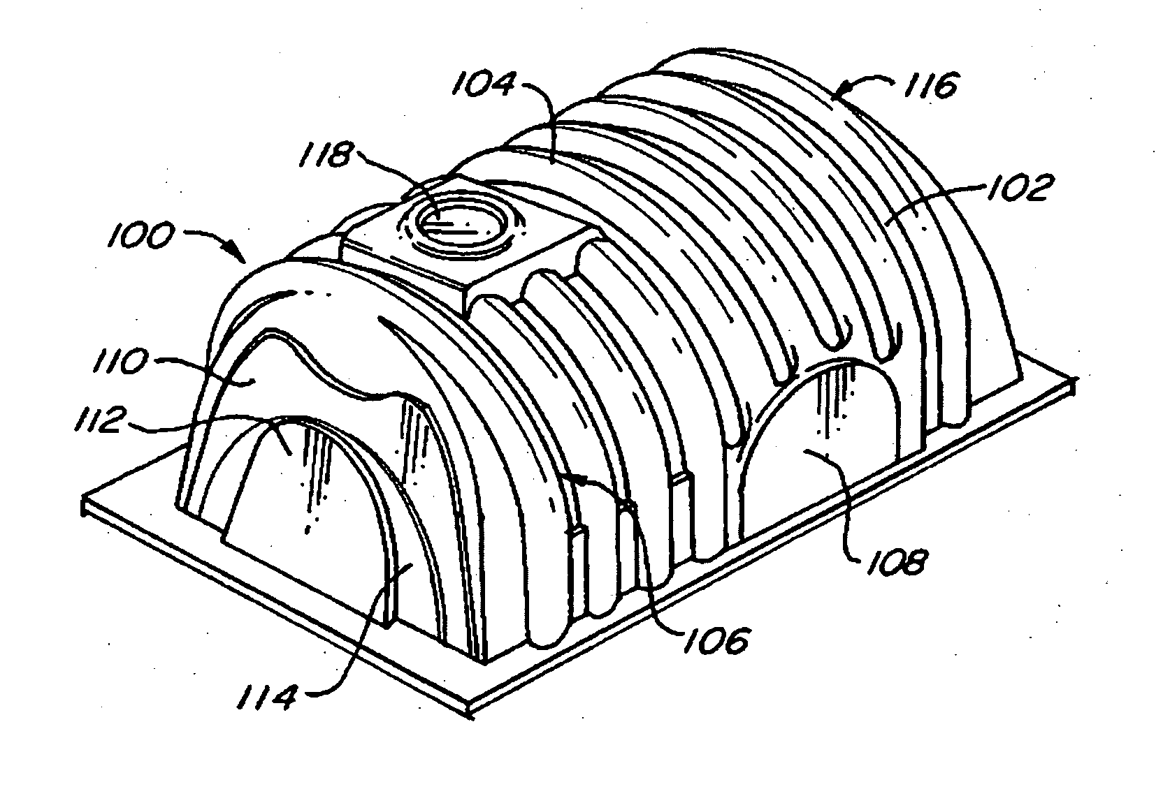
[0030] Turning now to FIG. 2 connection chamber 100 is illus...


PUM


Abstract

A connection chamber for waste water and storm water collection, the connection chamber including an arch-shaped cut out in a side thereof, the arch-shaped cut out sized to receive an arch-shaped row connector, which is provided to couple rows of chambers to each other. The coupling of various rows of chambers to each other facilitates to relatively even flow of fluid throughout the field of chambers.

Description

PRIOR APPLICATIONS [0001] This is a continuation-in-part of U.S. patent application Ser. No. 10 / 392,581 filed 20 Mar. 2003 in the name of Robert J. DiTullio and entitled “Storm Water Chamber for Ganging Together Multiple Chambers.”FIELD OF THE INVENTION [0002] The present invention relates generally to septic systems, and more particularly to a leaching or drainage system for a septic system which uses lightweight, molded chamber structures, which chamber structures are positioned so as to form an interconnected field for efficient distribution of fluid entering the chamber structures. BACKGROUND OF THE INVENTION [0003] Molded chamber structures are increasingly taking the place of concrete structures for use in leaching fields or to gather stormwater run off. Molded chamber structures provide a number of distinct advantages over traditional concrete tanks. For example, concrete tanks are extremely heavy requiring heavy construction equipment to put them in place. In leaching fields...

Claims


Application Information

Patent Timeline
IPC IPC(8): E02B13/00E03F1/00
CPCE03F1/003
Inventor DITULLIO, ROBERT
Owner ADVANCED DRAINAGE SYST
Why Eureka
Try Eureka