Combined recovery of hydrogen and hydrocarbon liquids from hydrogen-containing gases

a technology of hydrocarbon liquid and hydrogen-containing gas, which is applied in the direction of liquefaction, separation processes, lighting and heating apparatus, etc., can solve the problems of all or almost all known processes failing to apprecia

Inactive Publication Date: 2006-10-19
FLUOR TECH CORP
View PDF3 Cites 16 Cited by
  • Summary
  • Abstract
  • Description
  • Claims
  • Application Information

AI Technical Summary

Problems solved by technology

However, all or almost all of known processes fail to appreciate that hydrocarbons, and especially

Method used


Image

  • Combined recovery of hydrogen and hydrocarbon liquids from hydrogen-containing gases
  • Combined recovery of hydrogen and hydrocarbon liquids from hydrogen-containing gases

Examples


Embodiment Construction

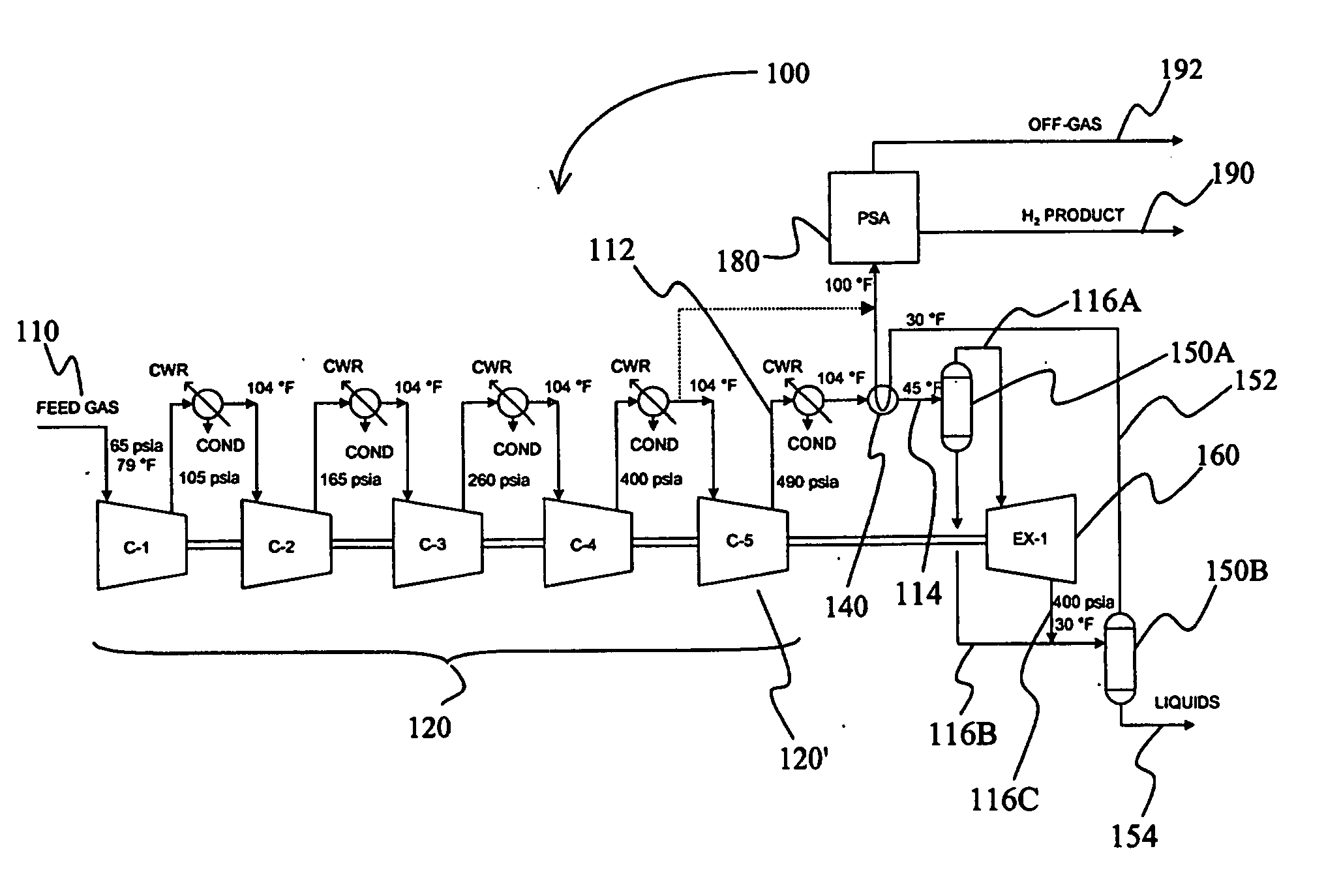
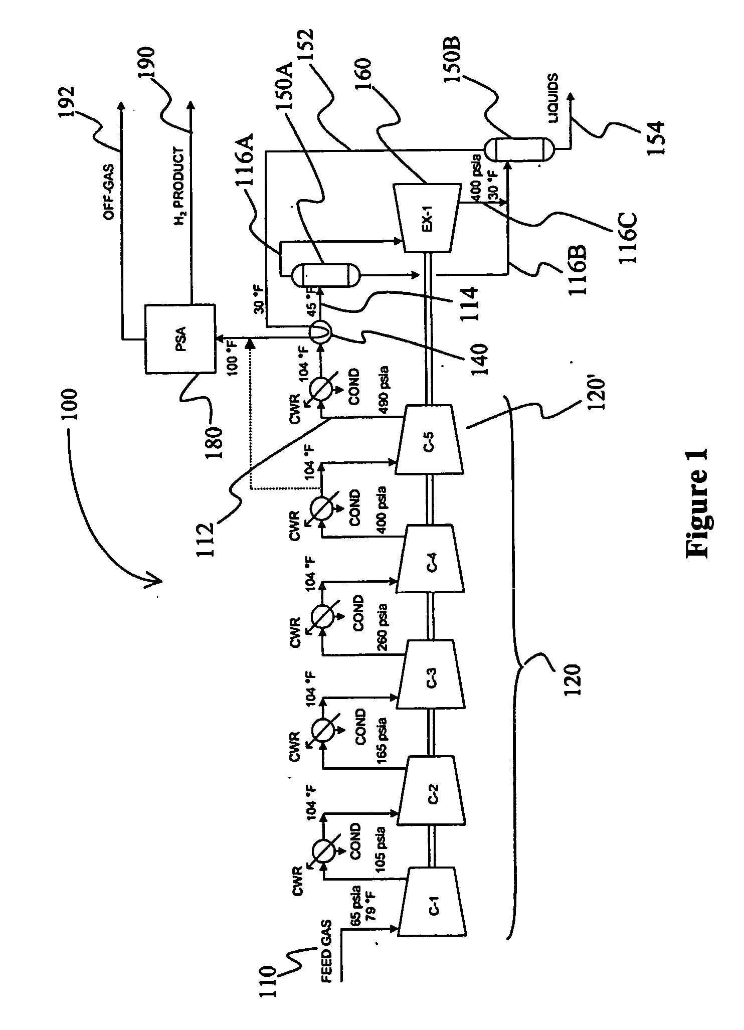
[0011] The inventor discovered that a pressure differential (e.g., between a compressor and an expander) of a feed gas can be employed to remove at least a portion of one component of the feed gas to produce a partially depleted feed gas from which another component may then be removed (e.g., using a pressure swing adsorption unit) in a fiuther processing step.

[0012] In one particularly contemplated aspect, a gas containing hydrogen and hydrocarbons is compressed to a first pressure P1. The compressed gas is subsequently further compressed to a second pressure P2. The compressed gas at P2 is expanded in an expander to P1, wherein ΔP (the pressure difference between P2 and P1) is sufficient to liquefy at least some of the hydrocarbon in the gas stream. A separator separates the liquefied hydrocarbon from the remaining compressed gas at P1, which is then fed into a hydrogen PSA unit in which hydrogen is recovered from the remaining compressed gas.

[0013] While it is generally contemp...


PUM


Abstract

A pressure differential of a feed gas (110) between a compressor (120) and expander (160) is employed to cool the feed gas to condense and remove at least a portion of one component to produce a partially depleted feed gas from which another component may then be removed. In especially preferred aspects, the feed gas comprises C2-C5 hydrocarbons and hydrogen, wherein the hydrocarbons are condensed in the cooler and hydrogen is removed using a pressure swing adsorption unit (180).

Description

[0001] This application claims the benefit of U.S. provisional patent application with the Ser. No. 60 / 342,262, which was filed Dec. 17, 2001, and which is incorporated herein by reference.FIELD OF THE INVENTION [0002] The field of the invention is gas processing. BACKGROUND OF THE INVENTION [0003] Numerous industrial processes, and especially processes in refineries and processing plants produce significant amounts of gaseous streams containing hydrogen and hydrocarbons. While in some known processes hydrogen and hydrocarbons from such streams are utilized as fuel, other known processes include a hydrogen recovery step (e.g. by employing a hydrogen PSA unit), and the resulting hydrogen-depleted hydrocarbon-containing stream is then utilized as a fuiel. However, all or almost all of known processes fail to appreciate that hydrocarbons, and especially hydrocarbon liquids, may be recovered from hydrogen-containing gases in a energy efficient process. Therefore, there is still a need f...

Claims


Application Information

Patent Timeline
IPC IPC(8): C07C7/00F25J3/00B01D53/00B01D53/047C01B3/50C01B3/56F25J3/06
CPCB01D53/002F25J2240/02B01D53/047B01D2256/16B01D2256/24B01D2257/702C01B3/506C01B3/56C01B2203/048C01B2203/0495F25J3/062F25J3/064F25J3/0655F25J2205/40F25J2205/60F25J2230/20B01D53/0446
Inventor REDDY, SATISH
Owner FLUOR TECH CORP
Why Eureka
Try Eureka