Eureka AIR delivers breakthrough ideas for toughest innovation challenges, trusted by R&D personnel around the world.

Cooking device

Active Publication Date: 2006-10-26
LG ELECTRONICS INC
View PDF10 Cites 40 Cited by
  • Summary
  • Abstract
  • Description
  • Claims
  • Application Information

AI Technical Summary

Benefits of technology

[0015] The present invention is designed to solve such a problem of the related art, and therefore, one object of the present invention is to provide a cooking device capable of preventing a user from being directly exposed to heat of a cooking chamber when the user opens a door of the cooking device.
[0016] Another object of the present invention is to provide a cooking device capable of enhancing cooling efficiency of its door.
[0017] Still another object of the present invention is to provide a cooking chamber capable of preventing a user from being exposed to heat of a cooking chamber with a simple structure.
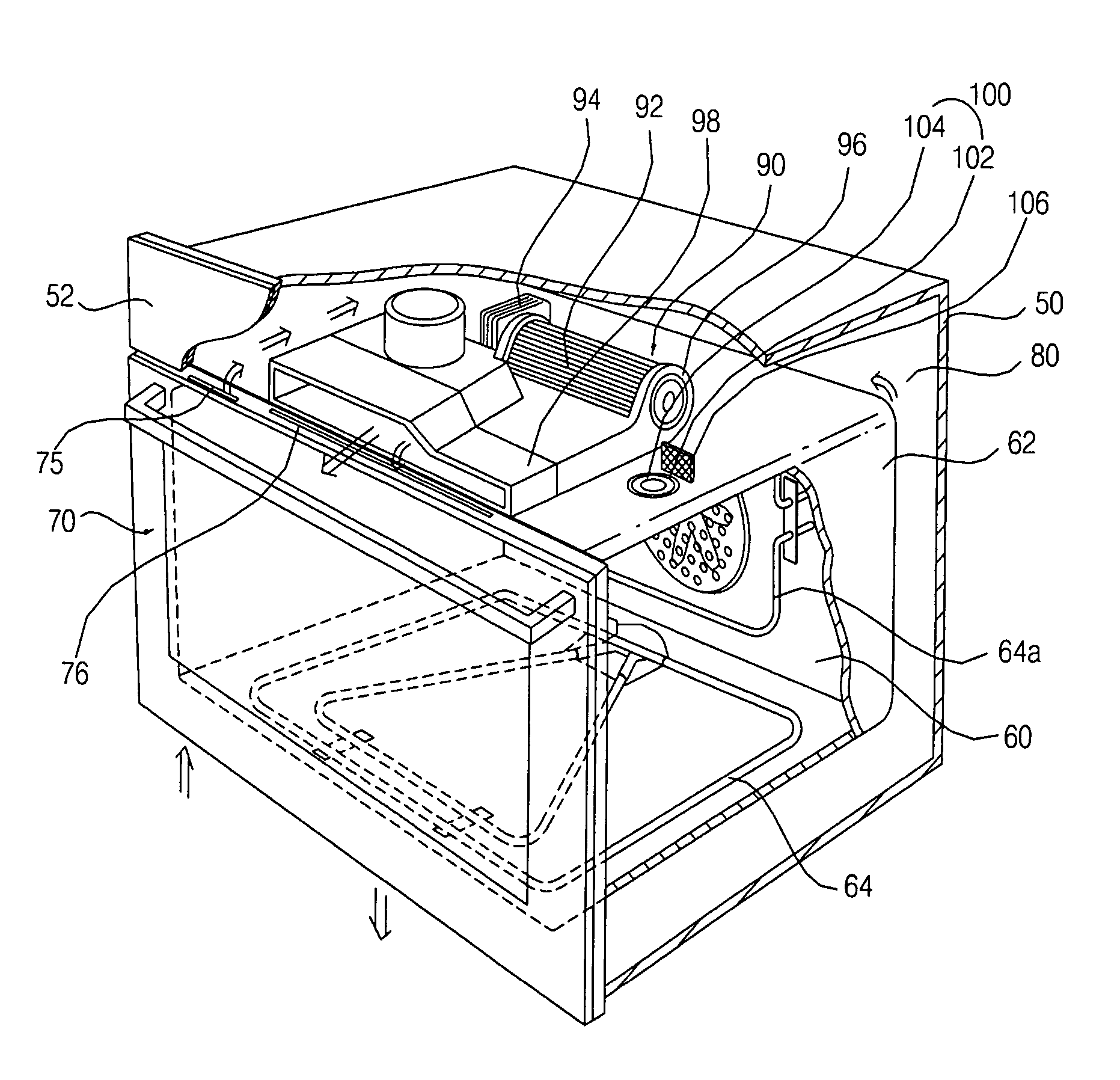
[0039] First, since air in the cooking chamber flows to the ventilation passage formed between the cabinet and the cavity by the cooking chamber air discharge unit and is cooled by air which passes through the ventilation passage and then discharged, when a user opens the door, high temperature air inside the cooking chamber can be prevented from being directly discharged to the user.
[0040] Second, because the cooking chamber air discharge unit includes the communicating passage for connecting the interior of the cavity with the ventilation passage and the valve for opening and closing the communicating passage, cooking or pyrolyzing can be effectively performed in a closing mode of the valve, and high temperature air can be effectively cooled and discharged in an opening mode of the valve.
[0043] Fifth, because the communicating passage is also formed in an opened state at the rear side of the cavity, high temperature air can be quickly sucked to the ventilation passage and cooled while cooking or pyrolysis cleaning is being performed.

Problems solved by technology

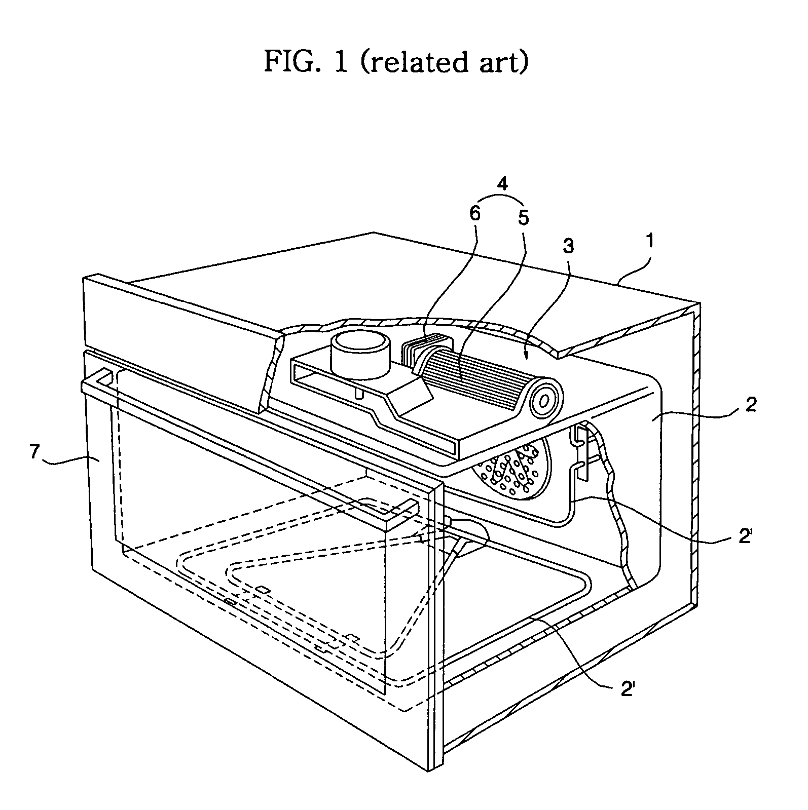
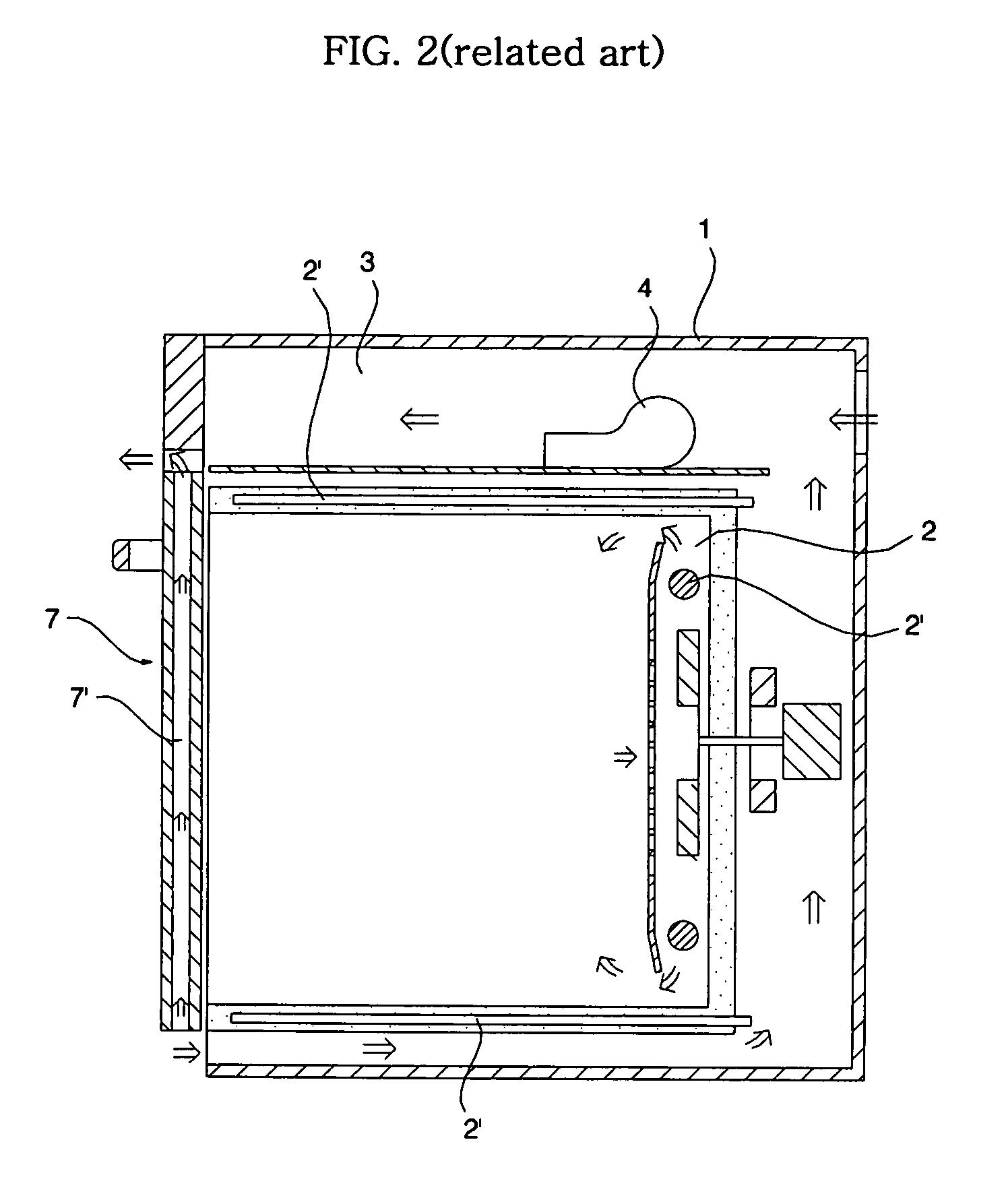
However, the related art cooking device has the following problems.
In this case, the internal air of the cooking chamber 2 is in a high temperature and high pressure state, including oil and moisture discharged from a food item therein, making the user feel uncomfortable, and in a worse case, a security problem, for example, the user could be burned, can arise.

Method used


Image

  • Cooking device
  • Cooking device
  • Cooking device

Examples


Embodiment Construction

[0056] A cooking device in accordance with preferred embodiments of the present invention will be described with reference to the accompanying drawings.

[0057] The embodiments of the present invention will now be described in detail with reference to the accompanying drawings.

[0058]FIG. 4 is a partially cut perspective view of a cooking device in accordance with one embodiment of the present invention, FIG. 5 is a side sectional view of the cooking device with its door closed in accordance with one embodiment of the present invention, and FIG. 6 is a side sectional view of the cooking device with its door opened in accordance with one embodiment of the present invention.

[0059] The cooking device in accordance with the present invention includes a cabinet 50 forming the exterior, a cavity 62 installed inside the cabinet 50 and having a cooking chamber therein 60, and a door 70 installed at the cabinet 50 to open and close the cooking chamber 60.

[0060] A control panel 52 is install...


PUM


Abstract

A cooking device includes a cabinet, a cavity installed in the cabinet and having a cooking chamber therein, a door installed at the cabinet to open and close the cooking chamber, a ventilation passage formed to allow external air of the cabinet to pass through between the cavity and the cabinet so as to be discharged, a blower installed in the ventilation passage, and a cooking chamber air discharge unit for discharging air from the interior of the cooking chamber through the ventilation passage. Because the heated air inside the cooking chamber can be cooled by air which passes through the ventilation passage and then discharged, when the door is opened, heated air cannot be directly discharged to a user from the cooking chamber.

Description

BACKGROUND OF THE INVENTION [0001] 1. Field of the Invention [0002] The present invention relates to a cooking device such as a microwave oven and, more particularly, to a cooking device capable of mixing heat generated as cooking or pyrolysis cleaning is performed in a cooking chamber with external cold air sucked to an electronic equipment chamber and discharging cooled air when its door is opened following the cooking or pyrolysis cleaning. [0003] 2. Description of the Related Art [0004]FIG. 1 is a partially cut perspective view of a cooking device in accordance with a related art, FIG. 2 is a side sectional view of the cooking device with its door closed in accordance with the related art, and FIG. 3 is a side sectional view of the cooking device when its door is opened in accordance with the related art. [0005] The cooking device as shown in FIGS. 1 to 3 includes a cabinet 1, a cooking chamber 2 provided in the cabinet 1 and is heated to perform cooking on a food item, a door 7...

Claims


Application Information

Patent Timeline
IPC IPC(8): F27D11/00A21B1/00A21B1/22
CPCF24C15/006F24C15/2007F24C15/04F24C7/085
Inventor KIM, JONG SIKSHIM, KYU IN
Owner LG ELECTRONICS INC
Why Eureka
Eureka Blog
Learn More