Normally open high flow hydraulic pressure control actuator

Inactive Publication Date: 2006-10-26
DELPHI TECH INC
View PDF18 Cites 22 Cited by
  • Summary
  • Abstract
  • Description
  • Claims
  • Application Information

AI Technical Summary

Benefits of technology

[0007] Generally, the present invention provides a unique side-fed, contra-seal, normally open hydraulic pressure control actuator configuration with a side supply port and an axial outlet port. The proposed valve configuration achieves the desired contra-seal mechanism in a much less complex and smaller package size. It is a pull-type design that allows the higher magnetic forces to occur when the rod / poppet surface encounter the highest hydraulic forces. Additionally, the spring preload can be small, only needing to be high enough to withstand the internal vibration forces that may tend to close the valve. This avoids the necessity of solenoid magnetic circuit over design and minimizes resultant costs.
[0009] According to another aspect of the invention, the valve member is poppet shaped and is integrally formed with the elongated control member. The rod extends coaxially through a center opening of an annular valve seat. This arrangement provides a structurally simple and robust design, which helps to minimize pressure drop within the valve.
[0012] According to still another aspect of the invention, the stop member is also operative to axially fix the valve seat within the valving bore by extending through aligned bores in said valving body wall and said valve seat. This arrangement has the advantage of simply and positively establishing the open end of travel of the valve element and ensures against any possible mispositioning of the valve seat, which, in turn, ensures positively establishing the closed end of travel of the valve element.
[0013] According to yet still another aspect of the invention, a surface feature is provided on the downstream, surface of the valve member facing the stop member, which, when in the open position, i.e. contacting, position, ensures against undesireable rotation or axial displacement if the valve member caused by fluid flow or vibration. This arrangement adds functionality to the solenoid-operated valve without adding cost, weight, part count or complexity.

Problems solved by technology

Additionally, the spring preload can be small, only needing to be high enough to withstand the internal vibration forces that may tend to close the valve.

Method used


Image

  • Normally open high flow hydraulic pressure control actuator
  • Normally open high flow hydraulic pressure control actuator
  • Normally open high flow hydraulic pressure control actuator

Examples


Embodiment Construction

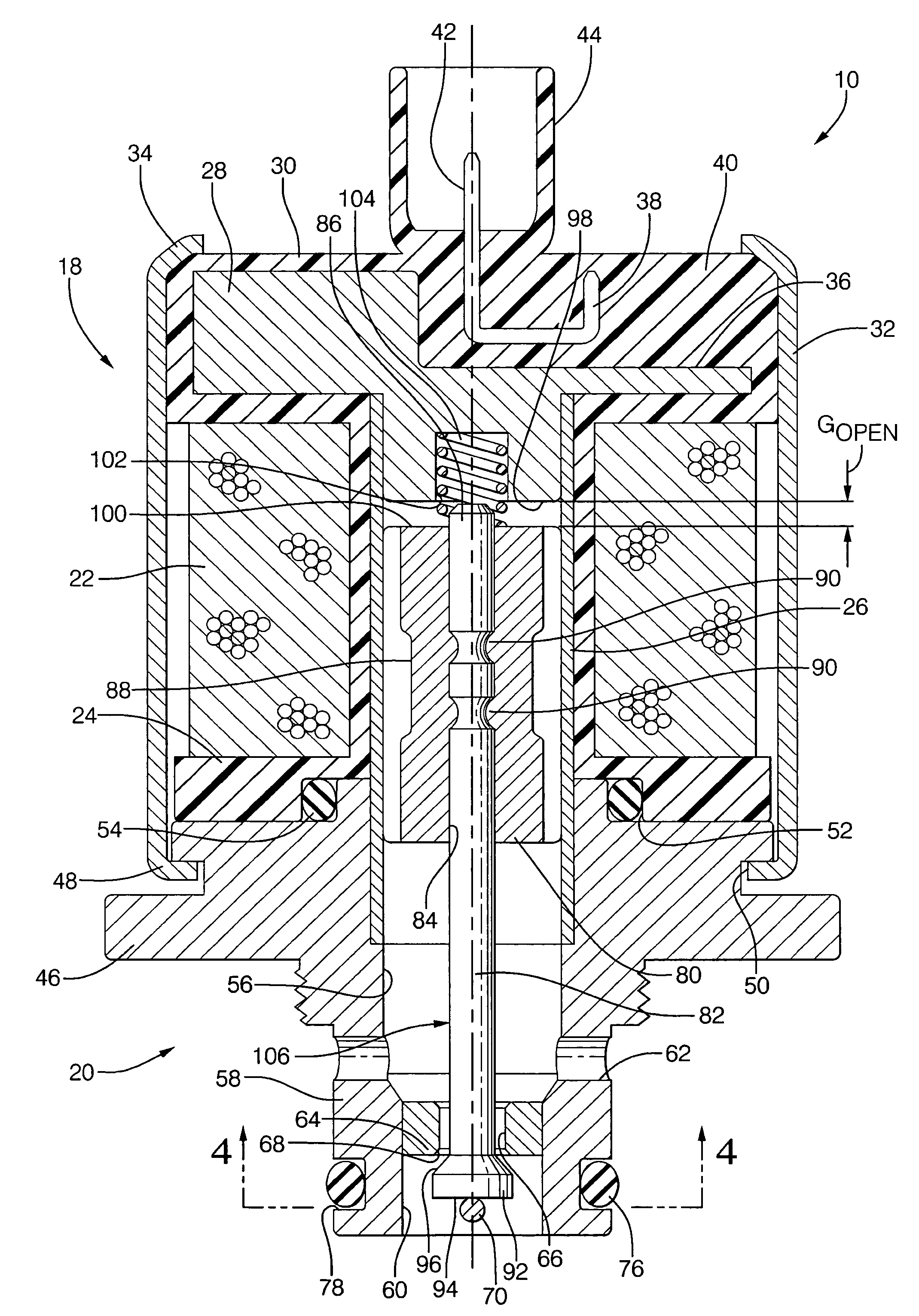
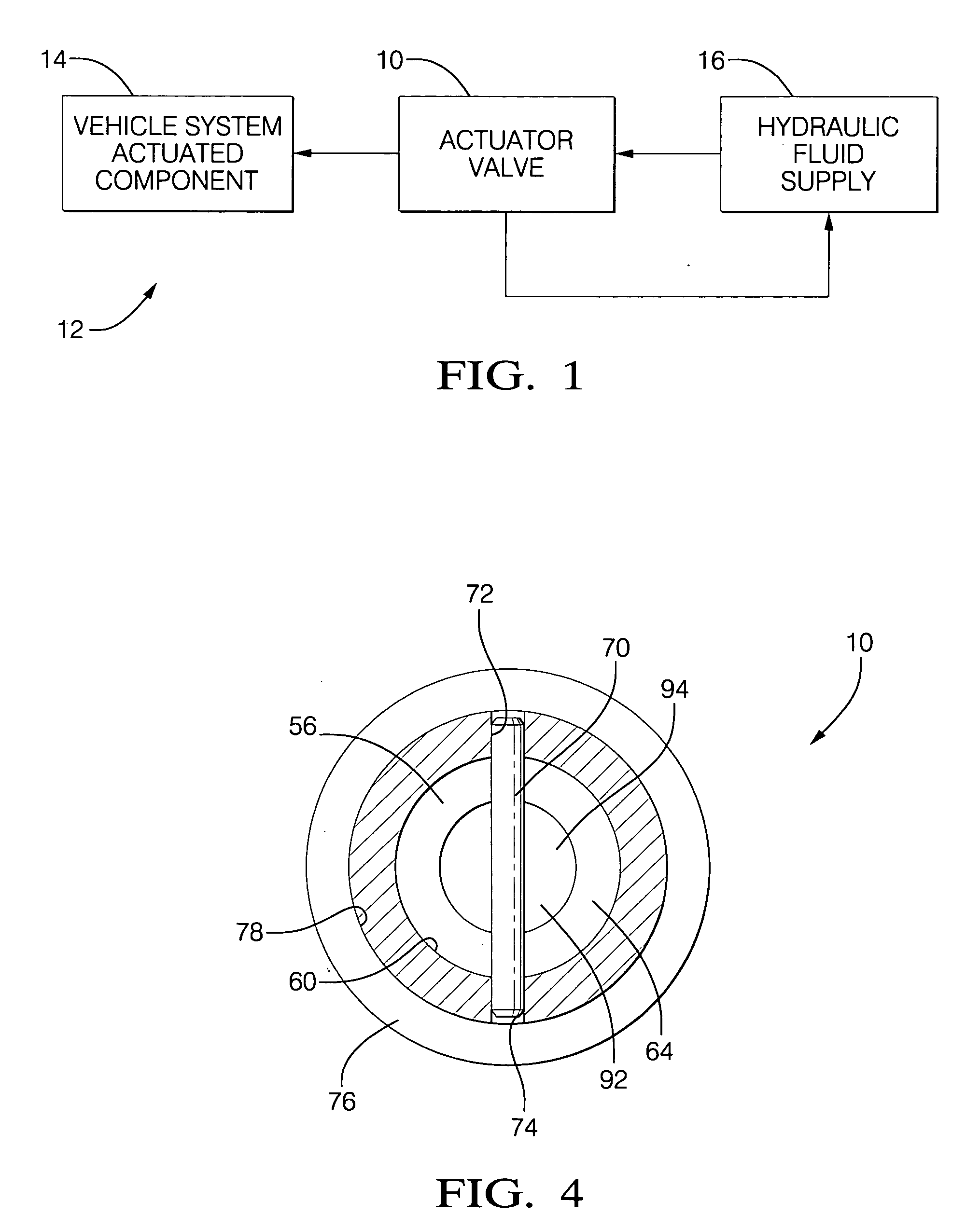
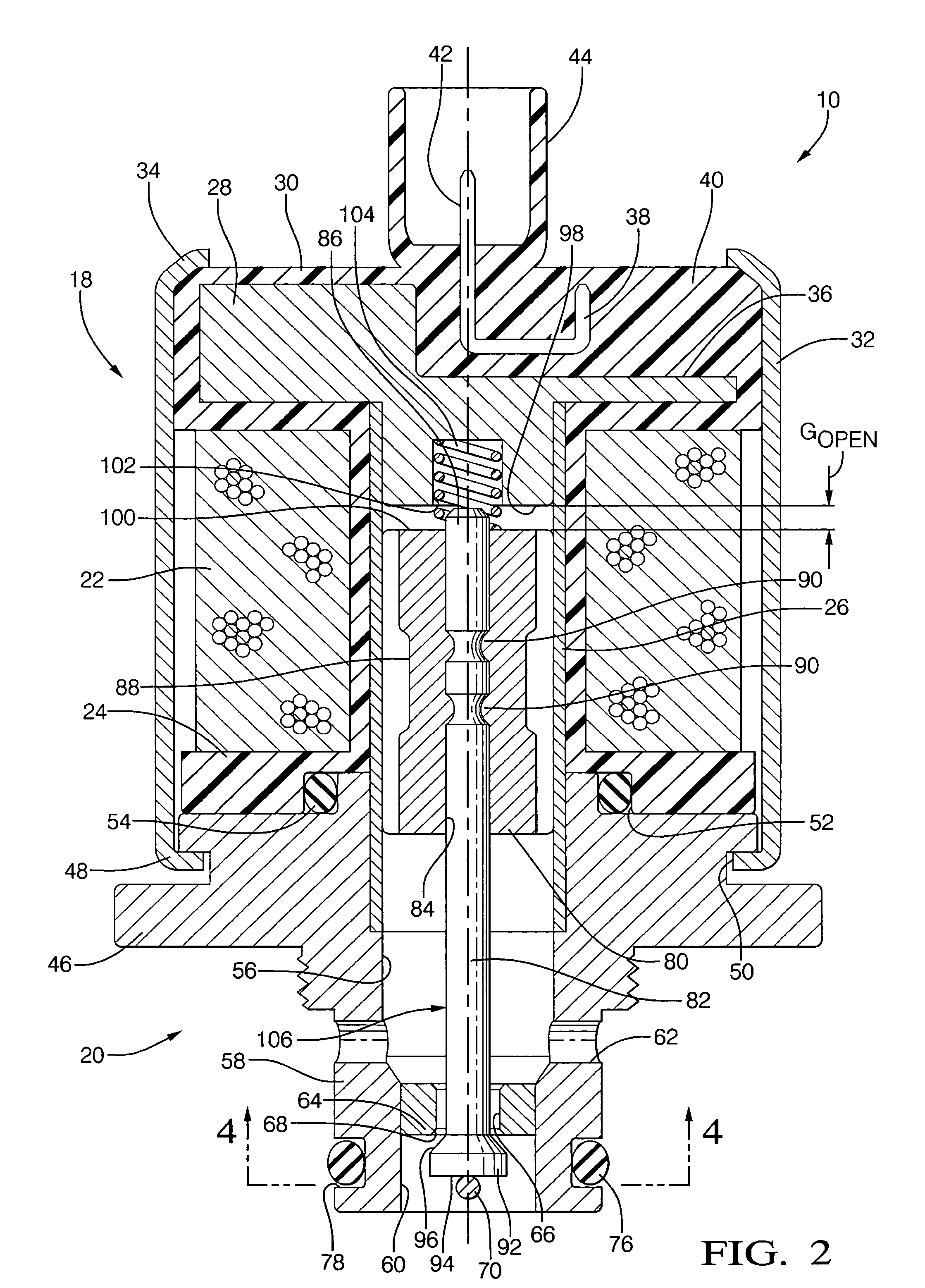
[0022] Referring initially to FIG. 1, a hydraulic pressure control actuator valve 10 is shown in a vehicle, generally designated 12. The valve 10 can be part of a fluid communication path of a control system of the vehicle 12 for operating a component 14 of the control system. The valve 10 may communicate with a hydraulic fluid supply reservoir 16.

[0023] The control system may be any suitable control system requiring actuators such as but not limited to transmission applications that use actuators to control the torque converter clutch (TCC) to smooth off-to-on position transitions, neutral-idle, and direct clutch gear shifting. The system may include various sensors and a processor in accordance with principals known in the art, with the processor selectively energizing and de-energizing the below-described coil of the actuator valve based on signals from the sensors as appropriate to control fluid flow through the system.

[0024] It is to be understood that while FIG. 2 shows a tw...


PUM


Abstract

A solenoid-operated valve includes a valve body defining a valving bore for providing a path of communication between axially spaced inlet and outlet ports. A solenoid assembly is attached to the valve body and includes an inductor coil, a fixed flux guide and an armature, which is movable axially between a first position and a second position in response to electrical energization of the inductor coil. A valve member is disposed within the valving bore intermediate the inlet and outlet ports. An elongated control member interconnects the armature and the valve member for conjoined axial movement. A generally annular valve seat is disposed within the valving bore between the inlet port and valve member, the valve seat including a central through bore through which the control member extends.

Description

TECHNICAL FIELD [0001] The present invention relates generally to hydraulic actuators, and more particularly, to solenoid operated hydraulic valves. More particularly still, the present invention relates to actuators suitable for application in automotive related hydraulic systems. BACKGROUND OF THE INVENTION [0002] Actuators, such as current-controlled, electro-hydraulic valves, are used in vehicles in anti-lock braking systems (ABS), traction control systems, stability control systems, automotive transmissions, and numerous other vehicular systems, as well as non-automotive industrial and commercial products. These valves typically use electrically controlled sliding plungers to selectively permit or prevent fluid flow through the actuator under particular circumstances, as required for the application. The plunger must be ferromagnetic, so that as current is passed through a wire coil that surrounds the plunger, the resulting magnetic force can move the plunger. Because of this a...

Claims


Application Information

Patent Timeline
IPC IPC(8): F16K31/02
CPCF16K31/0655Y10T137/7873
Inventor MORENO, ALEJANDROSUBRAMANIAN, VISWANATHANBURROLA, SANTOS
Owner DELPHI TECH INC
Why Eureka
Try Eureka