
Switching device, RF coil and magnetic resonance imaging system

a technology of magnetic resonance imaging and switching device, which is applied in the direction of measuring device, magnetic measurement, instruments, etc., can solve the problems of affecting the geometrical size of the switching apparatus the switching apparatus is affected by the required circuit characteristics, and the switching apparatus is even affected by the radiation loss of energy, so as to achieve the effect of reducing the geometrical size and reducing the radiation loss

Inactive Publication Date: 2006-10-26
GE MEDICAL SYST GLOBAL TECH CO LLC
View PDF28 Cites 15 Cited by
  • Summary
  • Abstract
  • Description
  • Claims
  • Application Information

AI Technical Summary

Benefits of technology

[0007] Therefore, an object of the present invention is to provide a switching apparatus capable of reducing a geometrical size while a radiation loss is being suppressed, an RF coil and a magnetic resonance imaging apparatus.
[0024] According to the switching apparatus of the present invention, a geometrical size can be reduced while a radiation loss is being suppressed.

Problems solved by technology

Since the frequency of a signal of the magnetic resonance imaging apparatus is relatively high, a radiation loss of energy occurs even in the switching apparatus.
If, however, the switching apparatus is configured by the distributed constant circuit, then the geometrical size of the switching apparatus is affected by required circuit characteristics.
If the coaxial cable of the distributed constant circuit is waved in accordance with the size of the RF coil, for example, then a manufacturing process becomes complex.

Method used


Image

  • Switching device, RF coil and magnetic resonance imaging system
  • Switching device, RF coil and magnetic resonance imaging system
  • Switching device, RF coil and magnetic resonance imaging system

Examples


first embodiment

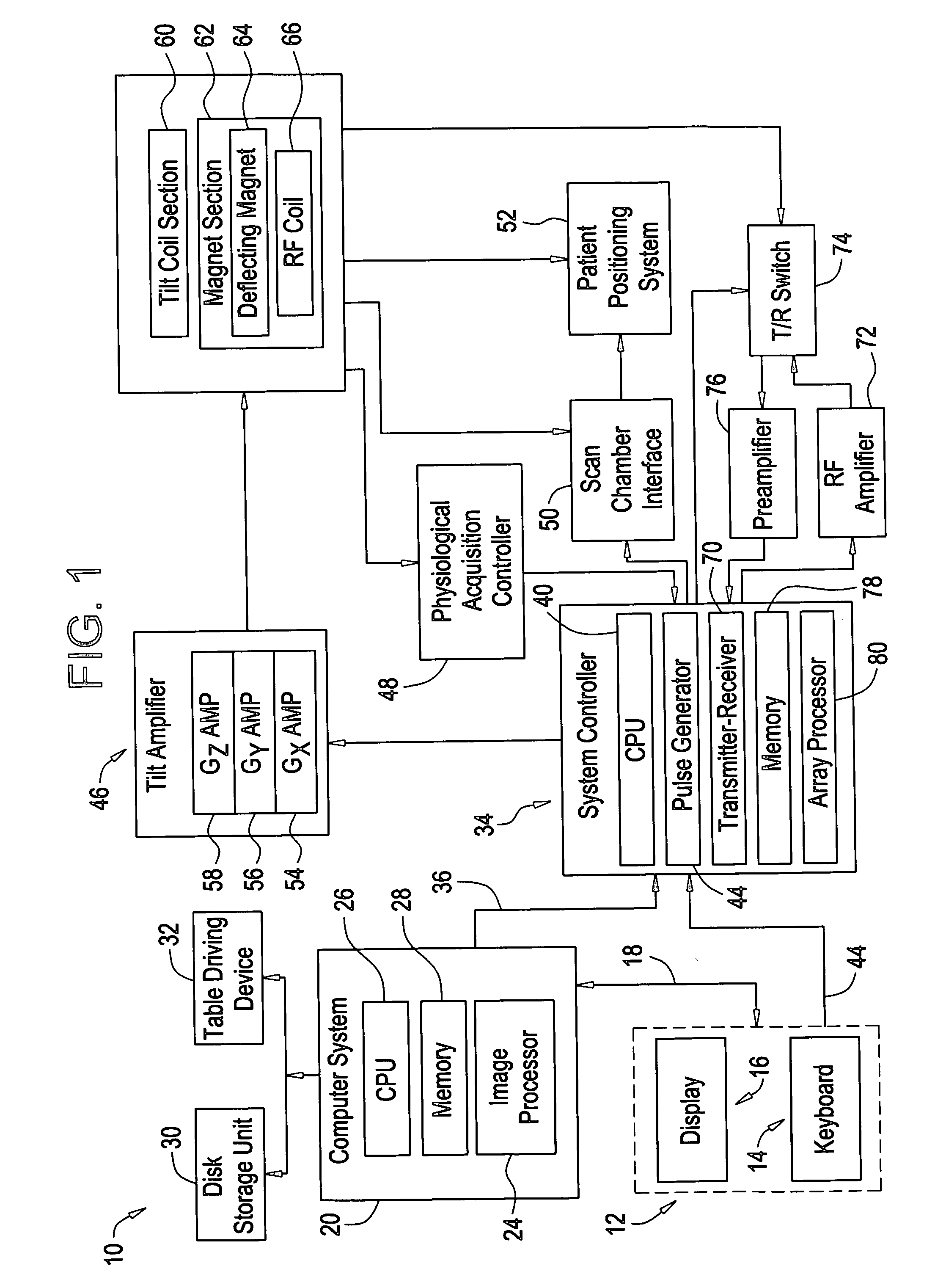
[0037]FIG. 1 is a block diagram of a magnetic resonance imaging apparatus (MRI) 10 according to a first embodiment of the present invention. The MRI 10 includes an operator console 12 including a keyboard and control panel 14, and a display 16. The operator console 12 is in communication with an independent computer system 20 via a link 18. Thus, an operator is able to control the creation and display of an image on the screen 16.

[0038] The computer system 20 includes a plurality of modules caused to communicate with one another through a backplane. For instance, the computer system 20 includes an image processor module 24, a CPU module 26, and a memory module 28 for storing an image data array therein, which might be called “frame buffer” in the present specification. The computer system 20 links a disk storage unit 30 and a tape driving device 32 to each other to facilitate storage of image data and programs. The computer system 20 communicates with an independent system controll...

second embodiment

[0077] An overall configuration of an MRI according to a second embodiment is similar to the first embodiment shown in FIGS. 1 and 2. Incidentally, constituents similar to the first embodiment are given reference numerals similar to those employed in the first embodiment below and their description will therefore be omitted. The MRI according to the second embodiment is different from the first embodiment in terms of the configuration of a switching apparatus.

[0078] A conventional switching apparatus will first be explained by referring to FIGS. 9 and 10, and a switching apparatus 210 according to the present embodiment will be described.

[0079]FIG. 9(a) is a circuit diagram showing a configuration of the conventional switching apparatus 210′, and FIG. 9(b) is a circuit diagram showing an equivalent circuit of the conventional switching apparatus 210′, respectively.

[0080] The switching apparatus 210′ is provided with semirigid coaxial cables 222′. The coaxial cable 222′ includes a...


PUM


Abstract

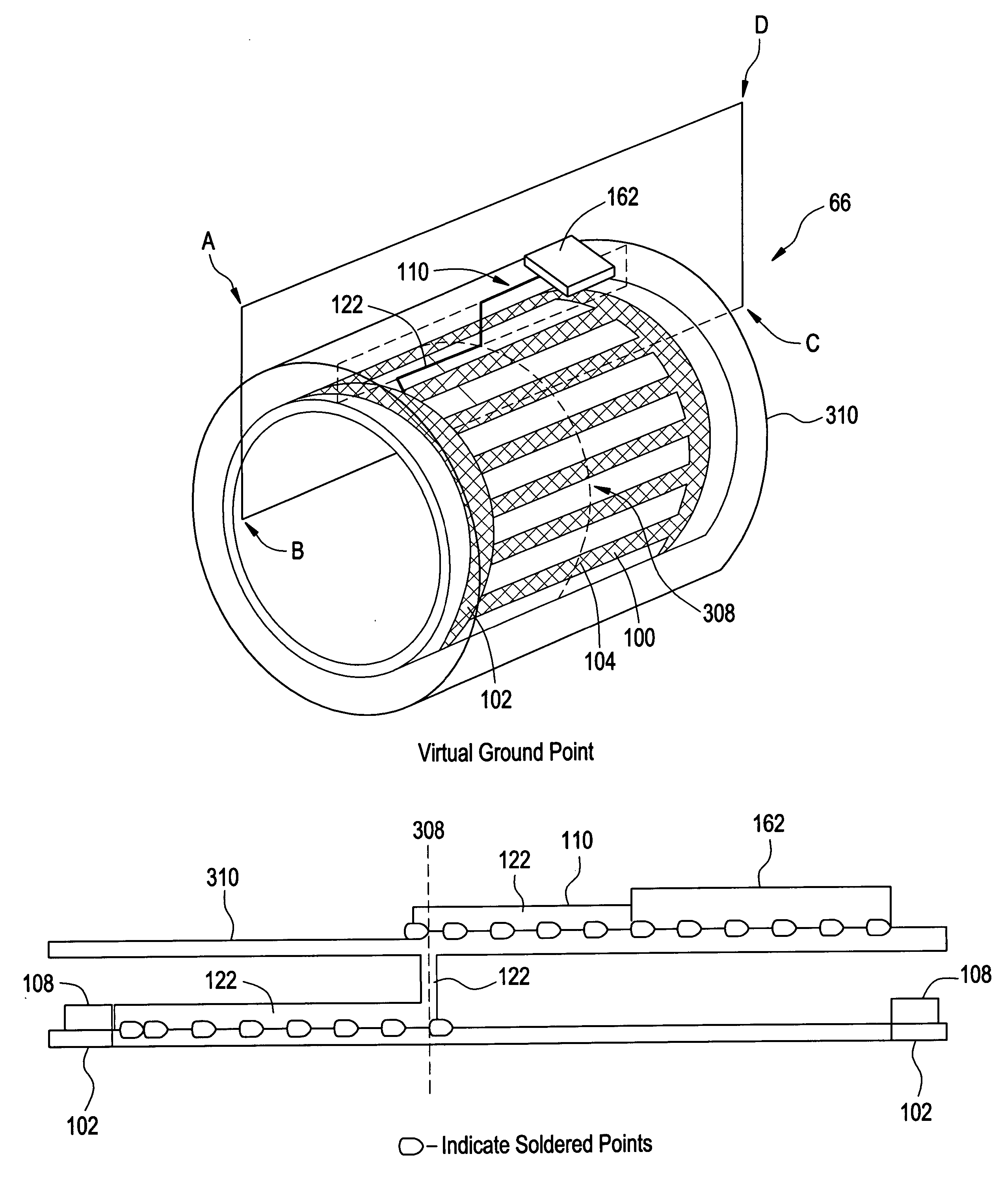
With the objective of providing a switching apparatus capable of reducing a geometrical size while a radiation loss is being suppressed, the switching apparatus that switches a state of an RF coil of an MRI between an effective state and an ineffective state, comprises a coaxial cable which has a length equal to ¼ of a wavelength corresponding to an operating frequency and in which an inner conductor and an outer conductor are connected to a coil body of the RF coil so as to interpose a capacitor therebetween, a diode connected to the inner conductor and outer conductor of the coaxial cable, and a capacitor corresponding to a lumped constant element connected to the inner conductor and outer conductor of the coaxial cable.

Description

CROSS REFERENCE TO RELATED APPLICATIONS [0001] This application claims the benefit of Japanese Application No. 2005-124733 filed Apr. 22, 2005. BACKGROUND OF THE INVENTION [0002] The present invention relates to a switching apparatus, an RF coil, and a magnetic resonance imaging apparatus. [0003] Since a plurality of RF coils (such as a body coil and a head coil) might be used in a magnetic resonance imaging apparatus, there is a need to avoid coupling among these RF coils. Therefore, there might be provided a switching apparatus for eliminating the characteristic as a resonant circuit by shifting a resonant frequency of a resonant loop or cutting the loop. Incidentally, the switching apparatus is generally identified by names such as “Dynamic disabling switch”, a detuner, etc. [0004] Since the frequency of a signal of the magnetic resonance imaging apparatus is relatively high, a radiation loss of energy occurs even in the switching apparatus. Therefore, a patent document 1 disclos...

Claims


Application Information

Patent Timeline
Patent Type & Authority Applications(United States)
IPC IPC(8): G01V3/00
CPCG01R33/34076G01R33/422G01R33/3657
Inventor NABETANI, AKIRA
Owner GE MEDICAL SYST GLOBAL TECH CO LLC
Learn More