Antenna device and antenna device manufacturing method

a technology of antenna devices and manufacturing methods, applied in the field of antenna devices, can solve problems such as difficulty in influencing voltage drops, and achieve the effect of simple operations

Inactive Publication Date: 2006-10-26
SONY CORP
View PDF8 Cites 10 Cited by
  • Summary
  • Abstract
  • Description
  • Claims
  • Application Information

AI Technical Summary

Benefits of technology

[0017] According to the above manufacturing method, it is possible to manufacture an antenna device in which the looped conductor portion is covered by the shield member and in which the non-covered portion

Problems solved by technology

This makes it difficult for the influence of a voltage fall due to co

Method used


Image

  • Antenna device and antenna device manufacturing method
  • Antenna device and antenna device manufacturing method
  • Antenna device and antenna device manufacturing method

Examples


first embodiment

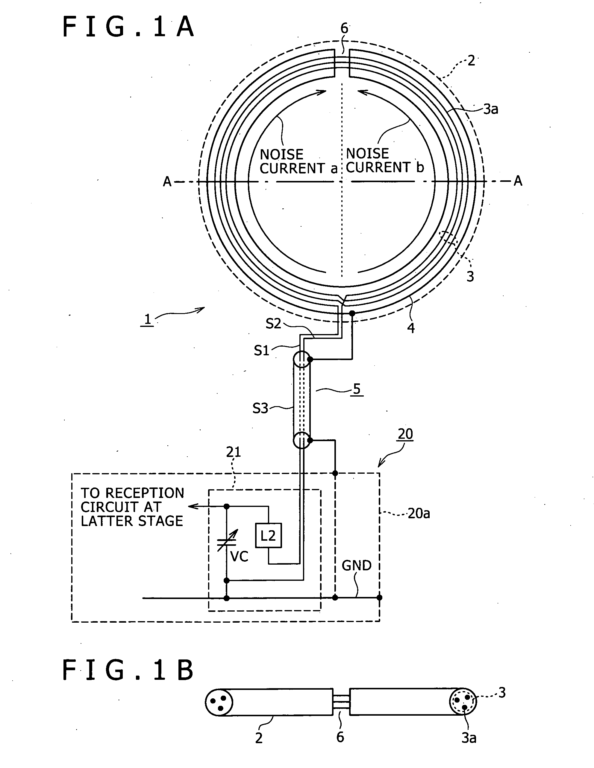
[0036]FIGS. 1A and 1B show an exemplary configuration of an AM antenna device 1 as the present invention. FIG. 1A is a view, from the front side, of the AM antenna device 1, and FIG. 1B shows a sectional view along line A-A of FIG. 1A.

[0037] As shown in FIGS. 1A and 1B, the AM antenna device 1 in this embodiment is composed of a loop antenna portion 2 including a looped conductor portion 3 and a shield pipe member 4, and a feeder 5 for connecting the loop antenna portion 2 to the reception circuit side of an AV apparatus 20 to thereby supply electric power.

[0038] In the loop antenna portion 2, the looped conductor portion 3 is formed in a structure in which a conductive wire 3a having a length corresponding to an inductance matched to the AM band is wound into a loop shape by a required number of turns. Incidentally, it should be noted here that a wire having an insulation coating, for example, a vinyl resin coating to a conductive core wire is used as the conductive wire 3a.

[0039...

second embodiment

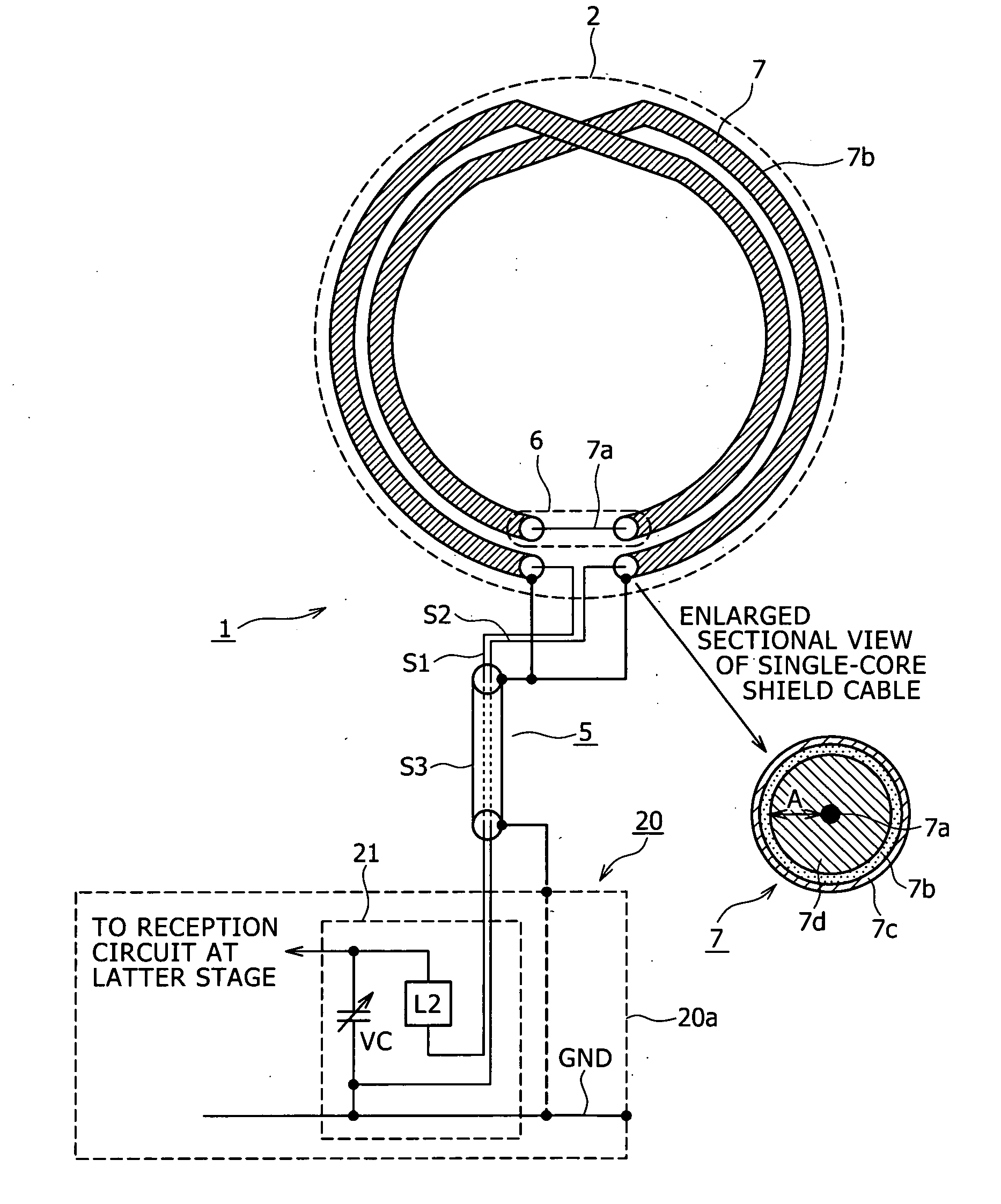
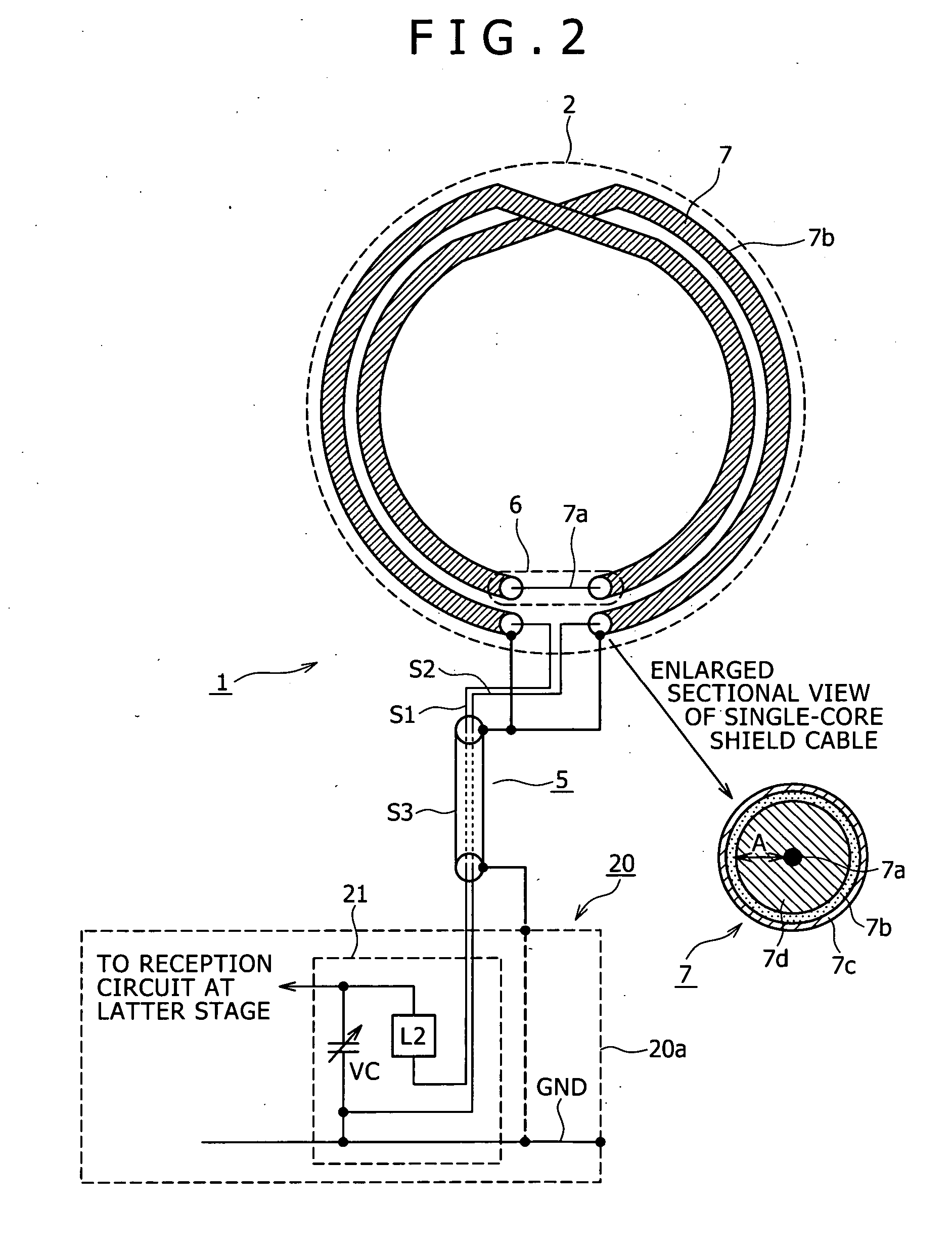
[0061]FIG. 2 shows an exemplary configuration of an AM antenna device 1 as a Incidentally, the same portion as those in FIGS. 1A and 1B are denoted by the same symbols as used above, and the same descriptions as above will be omitted.

[0062] A loop antenna portion 2 shown in FIG. 2 has a single-core shield cable 7. The single-core shield cable 7 is composed of a single core wire 7a, and a covered wire 7b for covering, and thereby shielding, the core wire 7a. The core wire 7a is provided with a predetermined length according to an inductance necessary for an AM antenna. The single-core shield cable 7 is formed into a loop shape by a predetermined number of turns.

[0063] In the loop antenna portion 2 formed in this manner, the core wire 7a corresponds to the conductive-wire 3a in FIGS. 1A and 1B, and the whole part of the loop shape of the core wire 7a formed attendant on the formation of the single-core shield cable 7 into a loop shape corresponds to the looped conductor portion 3. I...

third embodiment

[0077]FIGS. 3A and 3B show an AM antenna device 1 as a FIG. 3A is a view, from the front side, of the AM antenna device 1, and FIG. 3B is a sectional view along line A-A of FIG. 3A. Incidentally, in these figures also, the same portions as those in FIGS. 1A, 1B, and 2 are denoted by the same symbols as used above, and description thereof will be omitted.

[0078] First, a loop antenna portion 2 shown in FIGS. 3A and 3B is provided with a ring-shaped spool member 8. As seen from FIG. 3B, the spool member 8 is provided with a spool portion 8a which is roughly angular U-shaped in section. Incidentally, the shape of the spool portion 8a may be, for example, a roughly U-shaped sectional shape, or the like; it suffices for the sectional shape of the spool portion to have a portion opened to the outer periphery side of the ring-like shape.

[0079] In the spool portion 8a, as shown in the figures, a conductive wire 3a is wound to form a looped conductor portion 3, and the looped conductor port...


PUM


Abstract

A loop antenna device includes a loop antenna having a high noise resistance performance. In a loop antenna having a shield member covering a looped conductor portion formed in a loop shape from a conductive wire, a non-covered portion where the looped conductor portion is not covered is formed in correspondence with a portion of the conductive wire including a reference position for the symmetry of two terminals for connection between the antenna device and a reception circuit. This provides a balanced shield structure. Besides, a line for connecting one end of the conductive wire to the ground potential and a line for connecting the shield member to the ground potential are individually separate from each other, whereby reception of a voltage fall due to common impedance by the antenna is suppressed.

Description

TECHNICAL FIELD [0001] The present invention relates to an antenna device including a so-called loop antenna having a loop shape, and a method of manufacturing such an antenna device. BACKGROUND ART [0002] In AV apparatuses in recent years, a switching power supply circuit is mounted in many cases for reductions in power consumption and size, for example. It is known that the switching power supply circuit generates switching noises at comparatively high frequencies. In addition, in AV digital apparatuses represented, for example, by CD players, high-frequency noises are generated from digital circuits. In short, in the AV apparatuses and the like in recent years, there is a tendency of increases in high-frequency noises, as the so-called in-apparatus noises. [0003] Those AV apparatuses which incorporate a radio tuner have been wide spread. Where such an AV apparatus having a radio tuner is generating the above-mentioned in-apparatus noises, the antenna for receiving the radio broad...

Claims


Application Information

Patent Timeline
IPC IPC(8): H01Q11/12H01Q1/52H01P11/00H01Q7/02H01Q7/04
CPCH01Q7/04H01Q7/02H01Q1/526H01Q1/521H01Q1/40H01P11/001
Inventor MORIOKA, SUSUMUTAKANO, TAKASHISAEGUSA, SHIGERU
Owner SONY CORP
Why Eureka
Try Eureka