Small ultra-high NA catadioptric objective using aspheric surfaces

a catadioptric objective and aspheric surface technology, applied in the field of optical imaging, can solve the problems of chromatic correction becoming increasingly difficult in the duv region, providing nas lower than this ultra-high range, exhibiting small field size, and large optical element diameters

Inactive Publication Date: 2006-10-26
KLA TENCOR TECH CORP
View PDF21 Cites 17 Cited by
  • Summary
  • Abstract
  • Description
  • Claims
  • Application Information

AI Technical Summary

Problems solved by technology

However, chromatic correction becomes increasingly difficult for performance in the DUV region.
Certain previous designs can only provide NAs lower than this ultra-high range, and exhibit smaller field size, larger optical element diameters, or very tight tolerances in the high end applications discussed.
Previous ultra-high NA designs do not demonstrate this capability

Method used


Image

  • Small ultra-high NA catadioptric objective using aspheric surfaces
  • Small ultra-high NA catadioptric objective using aspheric surfaces
  • Small ultra-high NA catadioptric objective using aspheric surfaces

Examples


sixth embodiment

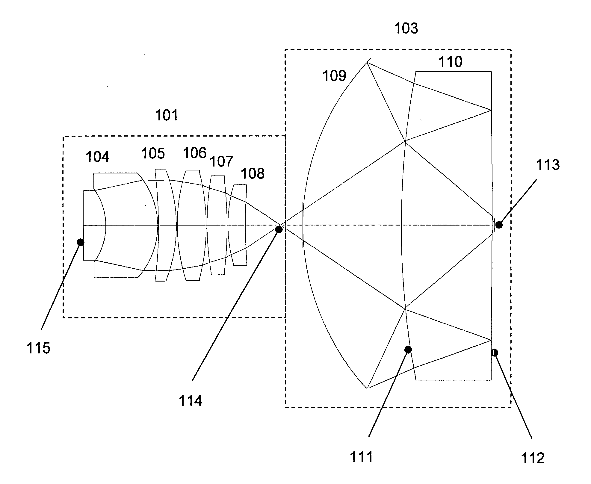
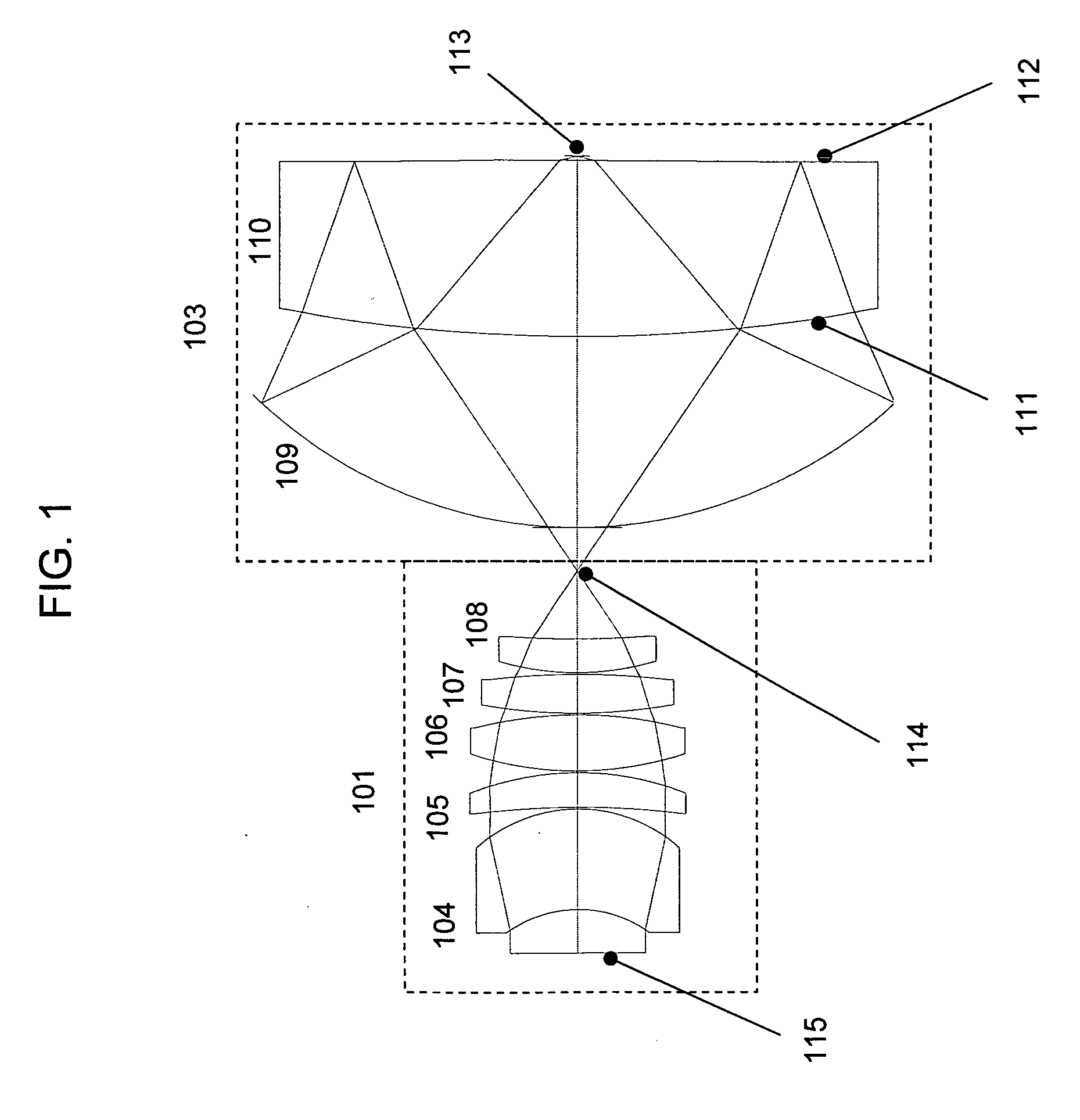
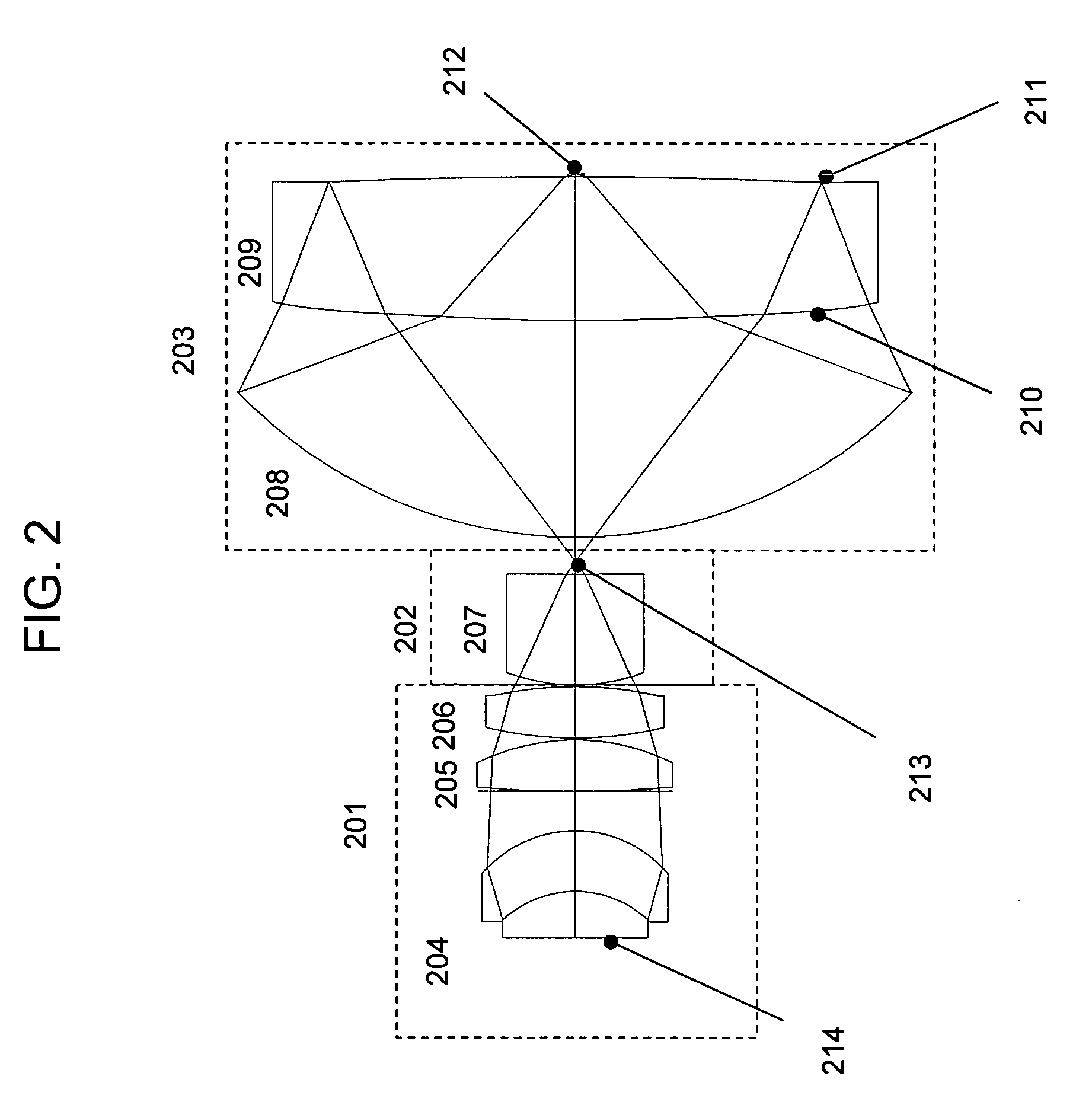
[0066]FIG. 2 illustrates a sixth embodiment according to the present design. The design comprises a focusing lens group 201 a field lens group 202 and a catadioptric group 203. The focusing lens group 201 includes lenses 204-206. Intermediate image 213 is formed by first lens group 201. This design includes a field lens 207 in proximity to the intermediate image 213. The intermediate image 213 is formed in proximity to the vertex of the spherical mirror 208 in catadioptric group 203. The catadioptric group comprises two elements including a spherical mirror 208 and a mangin element 209. In this design, sides 210 and 211 of the Mangin element 209 are aspheric.

[0067] The major difference between this lens prescription and the lens prescription in Table 1 and Table 2 is the optimization for a wavelength of 355 nm and a smaller 2.5 mm field size. This enables the reduction in the diameter of the elements and length of the objective as well as an improvement in the optical performance. I...

seventh embodiment

[0073]FIG. 3 illustrates a seventh embodiment according to the present design. The design of FIG. 3 comprises a focusing lens group 301, a field lens group 302, and a catadioptric group 303. The focusing lens group 301 includes lenses 304-307. Intermediate image 314 is formed by first lens group 301. This design includes a field lens 308 in proximity to the intermediate image 314. The intermediate image 314 is formed in proximity to the vertex of the spherical mirror 309 in catadioptric group 303. The catadioptric group comprises two elements including a spherical mirror 309 and a Mangin element 310. In this design, side 311 of the Mangin element 310 is aspheric.

[0074] The major difference between this lens prescription and the lens prescription in Tables 1 and 2 is the optimization for a smaller 11.0 mm field size and the use of only a single aspheric surface. This aspheric surface enables the reduction in the diameter of the elements and length of the objective as well as an impro...

eighth embodiment

[0080]FIG. 4 illustrates an eighth embodiment according to the present design that uses eight separate elements. The design comprises a focusing lens group 401, a field lens group 402, and a catadioptric group 403. The focusing lens group 401 includes lenses 404-407. Intermediate image 415 is formed by first lens group 401. The design further includes field lens 408 between the focusing lens group 401 and the intermediate image 415. The intermediate image 415 is formed in proximity to the vertex of the spherical mirror 409 in catadioptric group 403. The catadioptric group comprises three elements including a spherical mirror 409, lens element 410 used in triple pass, and a mangin element 411. The three element arrangement for the catadioptric group 403 places the lens 410 between the spherical mirror 409 and the Mangin element 411. This lens 410 is shaped as a meniscus element toward the spherical mirror 409. The side 412 of Mangin element 411 is aspheric while side 413 remains sphe...


PUM


Abstract

A relatively high NA objective employed for use in imaging a specimen and method for imaging a specimen is provided. The objective comprises a lens group having at least one focusing lens configured to receive light energy and form an intermediate image, at least one field lens oriented to receive the intermediate image and provide intermediate light energy, and a Mangin mirror arrangement positioned to receive the intermediate light energy and apply light energy to the specimen. One or more elements may employ an aspheric surface. The objective may provide, in certain instances, an uncorrected spectral bandwidth up to approximately 193 to 266 nanometers and can provide numerical apertures in excess of 0.9. Elements are less than 100 millimeters in diameter and may fit within a standard microscope. The field lens may comprise more than one lens and may be formed of a material different from at least one other lens in the objective.

Description

[0001] This application claims the benefit of U.S. Provisional Patent Application 60 / 667,237, “Small Ultra-high NA Catadioptric Objective Using Aspheric Surfaces,” filed Mar. 31, 2005, which is a continuation in part of U.S. patent application Ser. No. 11 / 093,850, entitled “Small Ultra-high NA Catadioptric Objective,” filed Mar. 29, 2005, which is a continuation-in-part of U.S. patent application Ser. No. 10 / 434,374, entitled “High Performance Catadioptric Imaging System,” inventors David G. Shafer, et al., filed May 7, 2003, which claims the benefit of U.S. Provisional Patent Application Ser. No. 60 / 449,326, entitled “High Performance, Low Cost Catadioptric Imaging System,” filed Feb. 21, 2003.BACKGROUND OF THE INVENTION [0002] 1. Field of the Invention [0003] The present invention relates generally to the field of optical imaging and more particularly to catadioptric optical systems used for microscopic imaging, inspection, and lithography applications. [0004] 2. Description of th...

Claims


Application Information

Patent Timeline
Patent Type & Authority Applications(United States)
IPC IPC(8): G02B23/00
CPCG02B21/04G02B17/0856
Inventor SHAFER, DAVID R.ARMSTRONG, J. JOSEPHCHUANG, YUNG-HO
Owner KLA TENCOR TECH CORP
Why Eureka
Try Eureka