Apparatus displaying three-dimensional image

Inactive Publication Date: 2006-10-26
KK TOSHIBA
View PDF4 Cites 50 Cited by
  • Summary
  • Abstract
  • Description
  • Claims
  • Application Information

AI Technical Summary

Benefits of technology

[0009] It is an object of the present invention to provide a three-dimensional display apparatus based on a multiview system or a one-dimensional IP sys

Problems solved by technology

It is difficult to maintain all the three characteristics at sufficient levels.
However, disadvantageously, this method insufficiently deals with crosstalk for each field resulting from time division multiplexing.
As describ

Method used


Image

  • Apparatus displaying three-dimensional image
  • Apparatus displaying three-dimensional image
  • Apparatus displaying three-dimensional image

Examples


first embodiment

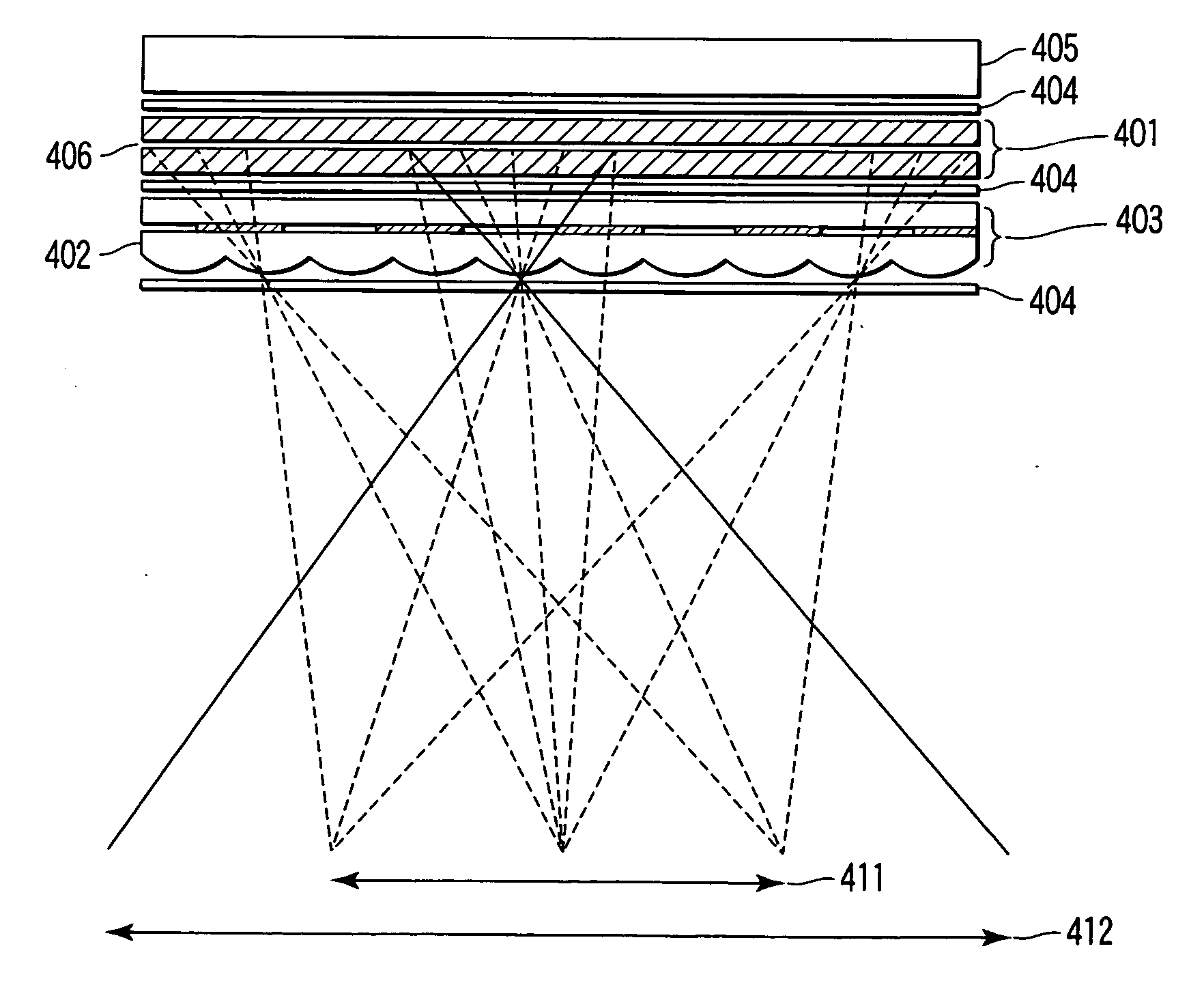
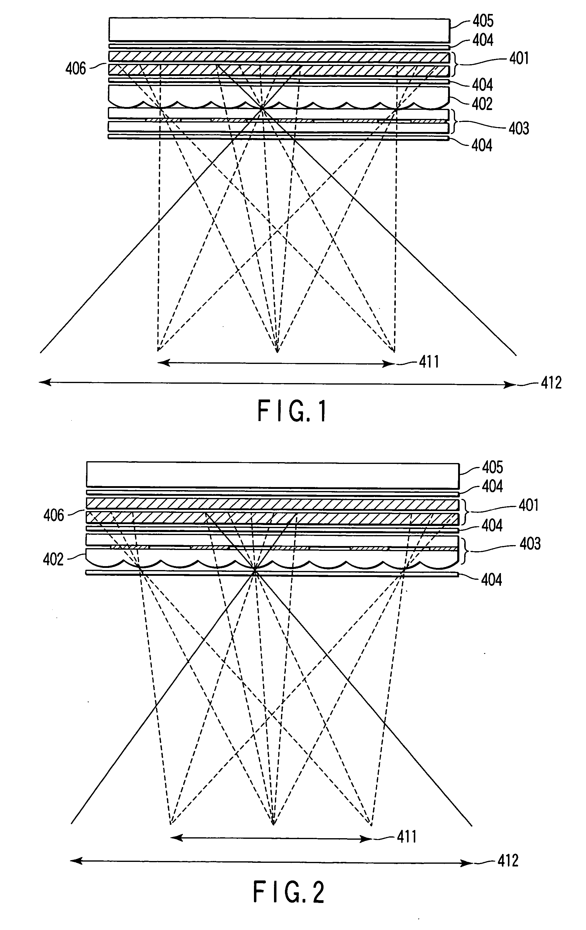
[0057]FIG. 1 is a horizontal sectional view schematically showing a three-dimensional image display apparatus in accordance with the present invention.

[0058] In the arrangement shown in FIG. 1, the bottom corresponds to an actual observer side. The top corresponds to a three-dimensional display apparatus side. In the three-dimensional display apparatus, a liquid crystal panel, i.e., a liquid crystal display module is adopted as a display module. As is well known, the liquid crystal panel is composed of a backlight unit 405, two polarizing plates 404, and a liquid crystal cell 401. In FIG. 1, reference numeral 406 denotes a pixel surface on which pixels are displayed, i.e. a display surface of the liquid crystal panel. The pixel surface 406 is substantially considered to be a surface on which pixels are arranged in a matrix in horizontal and vertical directions. Such a display apparatus is not limited to the liquid crystal panel. Naturally, the display module may obviously be a light...

fourth embodiment

[0099]FIG. 11 conceptually shows a part of a front view of the shutter cell 403 and lenticular plate adopted for a three-dimensional image display apparatus in accordance with the present invention. In this front view, the display screen is drawn from its upper end to lower end. However, the display screen is enlarged in a lateral direction and only partly shown. Accordingly, FIG. 11 shows only some of the shutter elements of the shutter cell 403, but the shutter cell 403 is actually placed so as to cover the entire pixel surface 406. The shutter cell 403 shown in FIG. 11 comprises a structure that switches between the transmitted state and the shutoff state for each shutter element the width of which is smaller than that of the lens and which is divided into areas extending obliquely to the lens. In this case, in the vertical direction, the shutter elements extend continuously from the end to end of the shutter cell and are not divided. However, each of the shutter elements may be ...


PUM


Abstract

In a three-dimensional image display apparatus in which a lenticular plate and shutter device are arranged in front of a display module, one frame image is displayed using n field images. To display each field image, a shutter device is driven to substantially simultaneously open a group of shutter elements for every n lenses along a horizontal direction. Thus, light beams are transmitted from lenses through the shutter elements to an observing zone. The group of the opened shutter elements is sequentially changed in response to n switchings of the field. The switching of shutter elements is synchronized with the pixels on the display surface sequentially rewritten from top to bottom by linear sequential driving during the switching of the field. The elemental image is projected on the viewing zone via the lenses and the shutter elements.

Description

CROSS-REFERENCE TO RELATED APPLICATIONS [0001] This application is based upon and claims the benefit of priority from prior Japanese Patent Application No. 2005-089646, filed Mar. 25, 2005, the entire contents of which are incorporated herein by reference. BACKGROUND OF THE INVENTION [0002] 1. Field of the Invention [0003] The present invention relates to an apparatus that displays three-dimensional images, and in particular, to a three-dimensional image display apparatus driven in a time division multiplexing manner. [0004] 2. Description of the Related Art [0005] There are various known systems for three-dimensional-vision image display apparatuses that can display three-dimensional motion pictures, that is, three-dimensional displays. In recent years, in particular, there has been a growing demand for a three-dimensional-vision image display system which is of a flat panel type and which does not require any dedicated glasses or the like. In relatively easily feasible known syste...

Claims


Application Information

Patent Timeline
IPC IPC(8): G02B27/24G02B30/27G02B30/31G02B30/60
CPCG02B27/2214G02B27/2264G09G3/003H04N13/0418G09G2300/023H04N13/0404H04N13/0415G09G3/3611H04N13/305H04N13/32H04N13/317G02B30/24G02B30/27G02B30/31
Inventor SAISHU, TATSUO
Owner KK TOSHIBA
Why Eureka
Try Eureka