Method of volume-panorama imaging processing

a volume-panorama and imaging technology, applied in the field of image data processing or generation, can solve the problems of inconvenient method with compound b-scanner, inability to utilize the general measurement function of ultrasonic to directly measure the size of the region, and the size of the single ultrasonic image that the doctor can see, etc., to achieve the effect of quickly and accurately generation

Active Publication Date: 2006-10-26
SHENZHEN MINDRAY BIO MEDICAL ELECTRONICS CO LTD
View PDF10 Cites 38 Cited by
  • Summary
  • Abstract
  • Description
  • Claims
  • Application Information

AI Technical Summary

Benefits of technology

[0029] The present invention has been conceived to solve the aforementioned problems in the prior art and to provide a method of volume-panorama imaging processing, capable of reconstructing a volume-panorama image quickly through splicing a series of partial images, obtaining a spliced volume-panorama image with a relatively high accuracy, and in particular meeting the very high requirement of the iatric ultrasonic apparatus for the diagnose of illness.
[0030] To solve the above technical problems, the basic concepts of the present invention are as follows: the elements for processing the volume-panorama imaging are a series of images arranged subsequently in term of time; the data correlation is generally the largest between data of the immediately adjacent image frames, i.e. there exists a relatively large overlapped region; during the procedure of splicing and extending a selected single image frame subsequently and continuously into the volume-panorama image based upon the first image frame, a aligned image and a spliced image can be established respectively for calculating a transform coefficient at the time of aligning the image Fi and splicing the image Fi to generate an output image; and the processing system self-adaptively adjusts the interval for picking up the image sequence based upon the current status (such as the cases of being too fast, too slow, an invalid alignment or the like), so as to ensure a quick execution of the processing and to improve the speed of the system and the reliability of the imaging. Furthermore, at the time of splicing the images, the processing system is also directed to the characteristic of changes of the image data, so that the characteristic points can be selected through a filtering with a threshold, and the alignment error can be reduced through filtering the motion vectors of the characteristic points with an index parameter, while improving the speed and the accuracy of the calculation results.
[0060] With the above methods, the object images can be generated quickly and accurately from the series of images obtained in a real-time way or stored in the medium, and the reliability of the generated volume-panorama object images can particularly meet a very high requirement of the ultrasonic apparatus for the iatric diagnose.

Problems solved by technology

However, the scanned area of a general probe is limited, resulting in a restriction on the size of the single ultrasonic image that the doctor can see.
Thus, when a region to be detected is located beyond an image, it is impossible to utilize the general measurement function of ultrasonic to directly measure the size of the region.
The method with the compound B-Scanner is very inconvenient due to its use of the mechanical arm.
Moreover, since the mechanical arm is not practical for the modern handhold ultrasonic probe, its development ends in the field of the image splicing.
a) With regard to the aspect of calculating the rotation angle between the images with the method of SAD: this method requires a range of rotation and a step interval for each rotation angle to be determined in advance, but the step interval for the angle is difficult to determine, in that the quantity of the calculation will increase and the speed will be slowed down if the interval is too small, and the accuracy of the calculation will be lowered if the interval is too large, for an accurate rotation angle may be between two calculation angles.
However, there is only an error of 0.5 pixel in the case of a direct splicing with the F1 and the F4.
Consequently, such sequential processing is not advantageous for reducing the error.
On the other hand, such sequential processing will lower the processing speed.
d) With regard to the aspect of calculating the offset with the SAD directly based upon data of each point within the regions divided from an image: in a case where the image has a large block of area in which the change of gradient is unobvious, this method will lower the accuracy of the calculation.
e) With regard to the aspect of calculating the transform coefficient with the based upon the local offset obtained with the SAD, particularly for the patent of U.S. Pat. No. 6,605,042 B2 for GE. Corp.: the experiments has proved that it is not the case that the offsets calculated from all the regions are correct due to noises of the ultrasonic images and organic movements, and consequently the transform coefficient may not be correct and result in a serious abnormity on the spliced image.

Method used


Image

  • Method of volume-panorama imaging processing
  • Method of volume-panorama imaging processing
  • Method of volume-panorama imaging processing

Examples


first embodiment

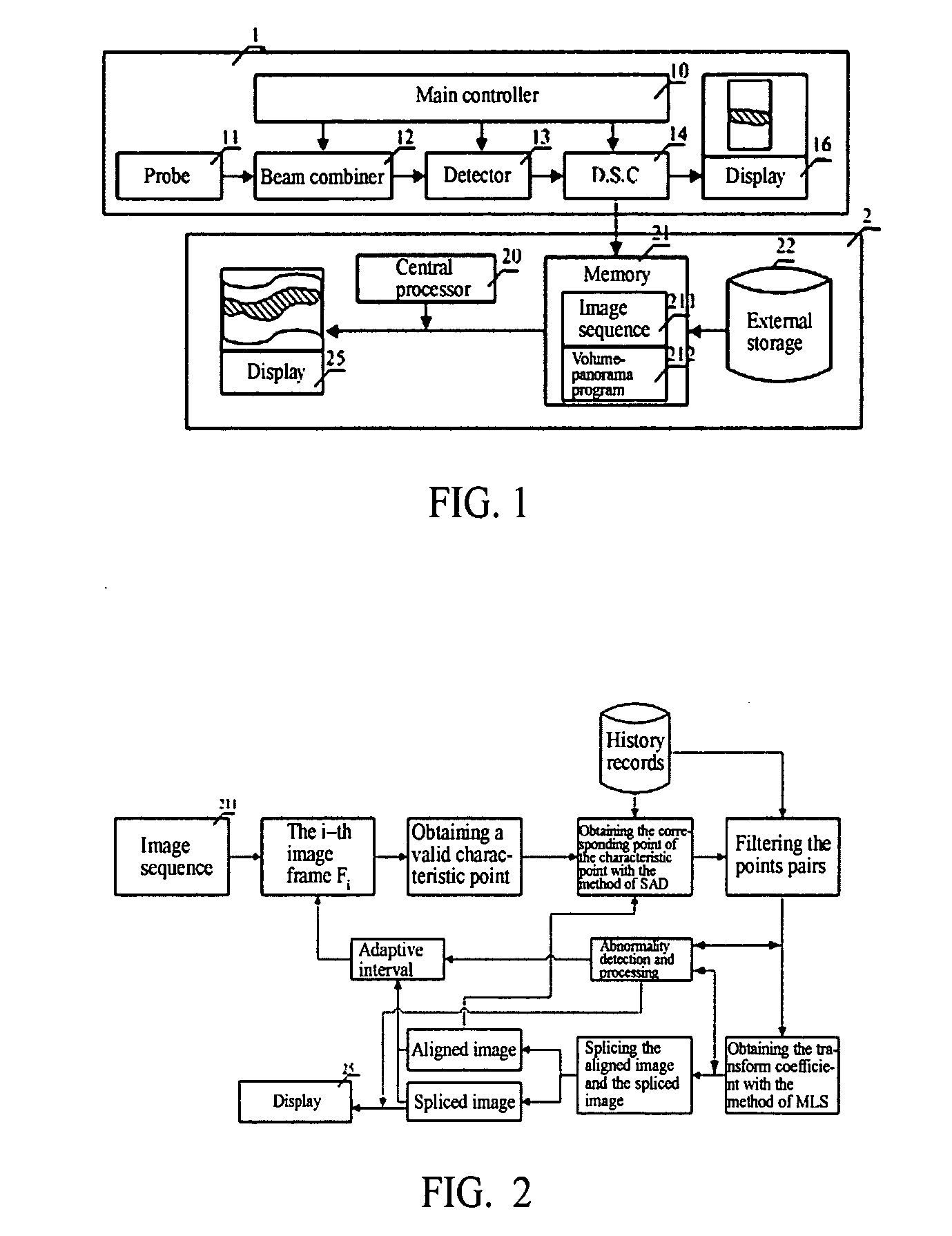
[0070] The serial number i of the image is 1, 2, 3 . . . , and Δ is an interval for picking up the image sequence. The method according to the invention comprises the steps of:

[0071] a. obtaining the image sequence, and initializing an aligned image and a spliced image as a first image frame, where i=2 and Δ=1;

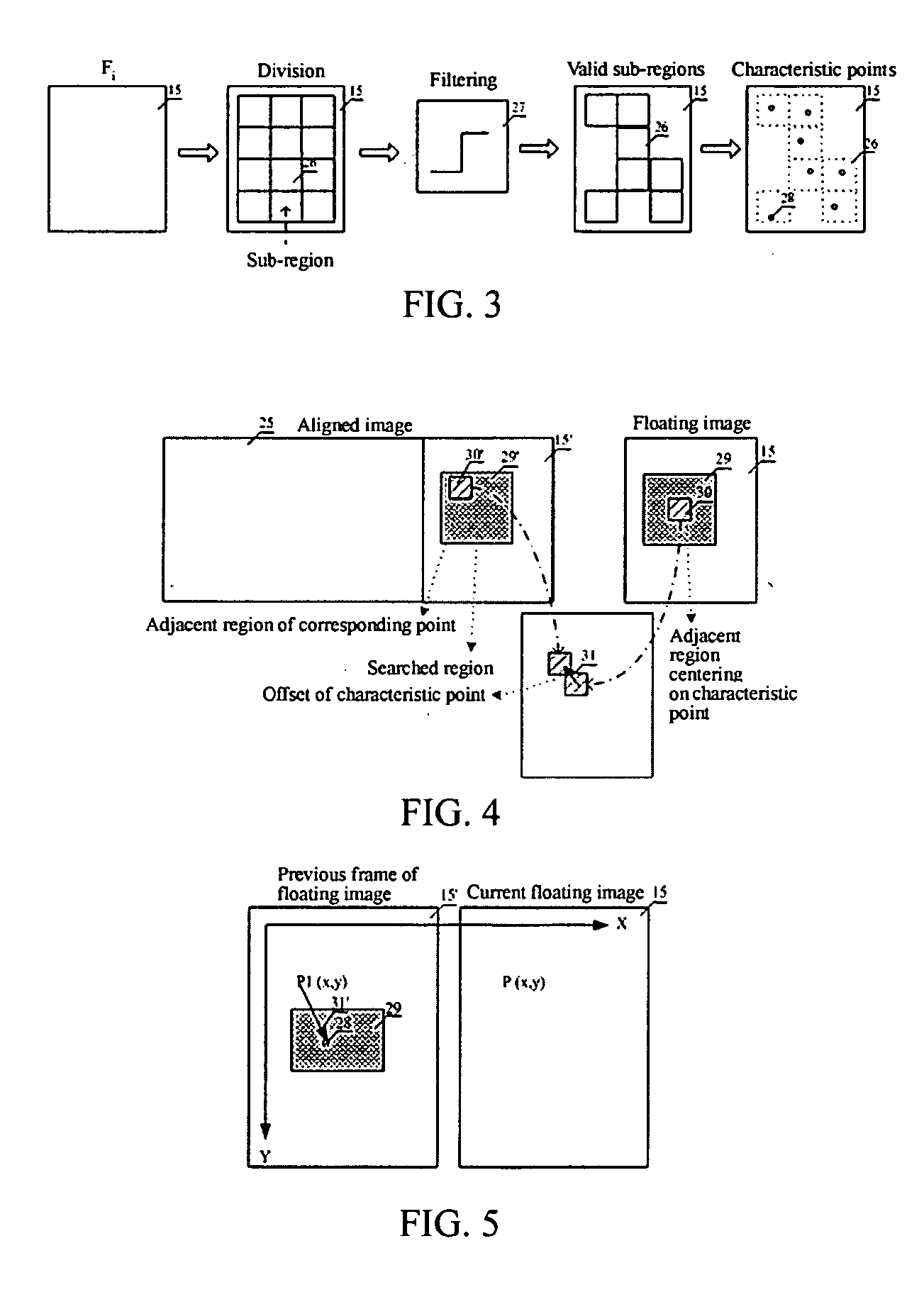
[0072] b. dividing the i-th image frame Fi into a plurality of sub-regions;

[0073] c. calculating a motion vector of the i-th image frame with respect to the aligned image;

[0074] d. calculating a transform coefficient based upon a fitting of the motion vector;

[0075] e. splicing the Fi to the current spliced image based upon the transform coefficient, and configuring or splicing the aligned image with the Fi; and

[0076] f. i=i+Δ, and returning to the step of b if the i-th frame exists, otherwise outputting the current spliced image as a resultant image.

[0077] The above steps relate to two main procedures of alignment and splicing. The former is used to obtain the transform ...

case 1

[0094] The quality of a single image frame is unreliable and no calculation is performed with the MLS. This case occurs in the double filtering during the alignment, including one filtering for selecting characteristic points and the other filtering of motion vectors. If the number of valid point pairs of the characteristic points and the corresponding points (motion vectors) is smaller than a preset number after the double filtering (possibly in that the correlation may be too poor due to a too large translation amount of the Fi relative to its previous image or any other factor), then the image frame will not be subject to the final splicing.

case 2

[0095] The offset of the transform coefficient calculated with the MLS appears abnormal (too fast or too slow). This case may be due to any problem of input data (the previous and the subsequent frames are incoherent) or due to an inaccuracy of the above interval preset through the prediction, wherein the calculated motion vector may be too large or small if the interval is too large or small.

[0096] As for any of the above cases, the image frame will not be subject to the subsequent splicing (i.e. the step of e), and a return procedure will be executed to go back to the initial state prior to the processing of the frame. Meanwhile, the interval for picking up the image sequence will be adjusted self-adaptively for executing the processing of another frame.

[0097] When there occurs the cases, including the case 1, continuously several times in which the subsequent splicing is not performed, the system can judge that the part of the image among the image sequence is undesirable in qu...


PUM


Abstract

The present invention discloses a method of volume-panorama imaging processing, which generates a volume-panorama image by subsequently splicing respective image frames from an image sequence obtained in a real-time way or stored in a medium based upon the fact that the immediately adjacent image frames have the largest correlation. The method comprises the steps of: reading the image sequence, and firstly initializing an aligned image and a spliced image; dividing the i-th image frame Fi into a plurality of sub-regions; calculating a motion vector of the i-t image frame with respect to the aligned image; fitting the motion vector to calculate a transform coefficient; splicing the Fi to the current spliced image based upon the transform coefficient, and updating the aligned image; entering into a self-adaptive selection of a next image frame until the end of the splicing; and outputting the current spliced image as a resultant image. Additionally, when the image Fi is spliced, double-filtering architecture of selecting characteristic points through a filtering and selecting the valid motion vector of the selected characteristic points through the other filtering to reduce an alignment error may be adopted. According to the present invention, the volume-panorama imaging can be done quickly and accurately so that the reliability of images particularly meets a very high requirement of the ultrasonic iatric diagnose.

Description

FIELD OF THE INVENTION [0001] The present invention relates to image data processing or generation, and particularly to a method of data processing or generation, which splices a plurality of two-dimensional images into a single image. BACKGROUND OF THE INVENTION [0002]“Volume-Panorama-Imaging” refers to such a technique that splices a series of two-dimensional images into one continuous image, which are obtained through moving a probe within the same plane. Due to a relatively large quantity of processed data, this technique generally utilizes a high-speed processor or computer to reconstruct the single image, and becomes increasingly widely used in the field of data pick-up in which a relatively large object is sensed with a minor probe, such as the acquisition of a fingerprint with a tiny probe. Particularly in the field of medical ultrasonic imaging, there is a higher requirement and a wide demand for the technique for the purpose of the aided iatric diagnosis. [0003] Taking an ...

Claims


Application Information

Patent Timeline
Patent Type & Authority Applications(United States)
IPC IPC(8): G06K9/36G06V10/24
CPCG06K9/32G06K2009/2045G06T7/0026G06T2207/30004G06T7/2026G06T2207/10132G06T2207/20021G06T7/0028G06T7/32G06T7/33G06T7/238G06V10/16G06V10/24
Inventor DONG, JIANNI, DONGYAO, BIN
Owner SHENZHEN MINDRAY BIO MEDICAL ELECTRONICS CO LTD
Why Eureka
Try Eureka