
Centrifuge with shaping of feed chamber to reduce wear

Active Publication Date: 2006-10-26
LANTZ EDWARD CARL
View PDF0 Cites 6 Cited by
  • Summary
  • Abstract
  • Description
  • Claims
  • Application Information

AI Technical Summary

Benefits of technology

[0064] Preferably each discharge surface is shaped, relative to the imaginary plane, such that a portion of the discharge surface adjacent the trailing edge of said one of the outlets lies generally in the imaginary plane. This forms a sharp edge at the junction with the wall of the rotor which can better engage the slurry within the rotor.
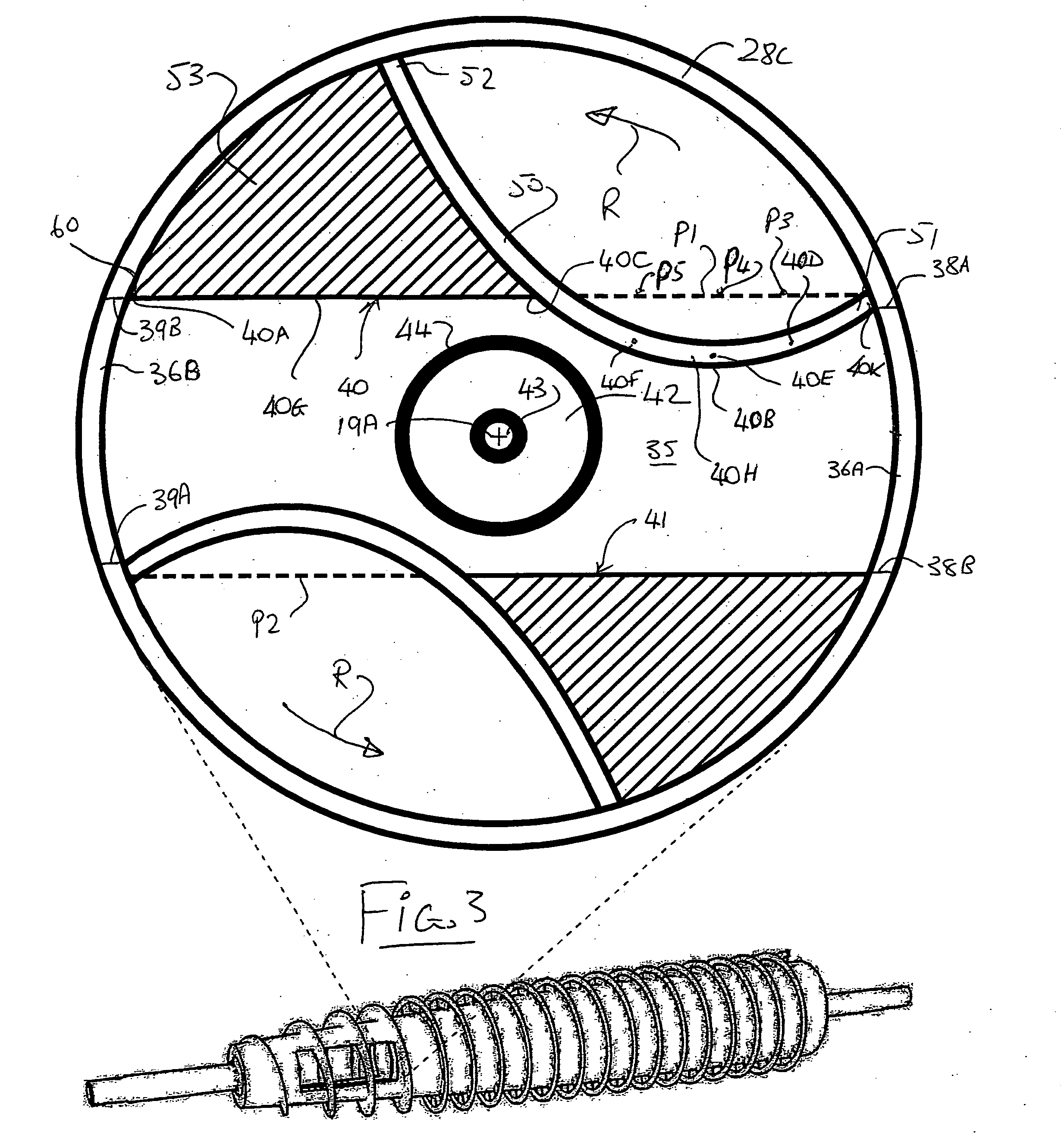
[0065] Thus the accelerator plate is dominated by a “striker nose” that protrudes into the feed chamber. This adaptation can operate to eliminate splash-back, positions the flow, increases optimal performance of the auger, and minimizes wear by forcing the solids to wear onto other solids and avoid wearing on steel.
[0066] In addition, the slurry passes over the base of the feed chamber which has been re-designed with a curved surface to facilitate easier movement of solids and to make the area more resistant to wear. This area has been accentuated to easier facilitate flow. By building up the height of the discharge edge or trailing of the feed chamber and giving it a slope, a path of least resistance is achieved.
[0067] After passing through the feed chamber, the slurry strikes an accelerator plate and is forced into the bowl. The accelerator plate has been designed to more readily force the materials into the bowl for separation.

Problems solved by technology

The greatest difficulty in achieving optimal performance in a centrifuge of this type is wear caused by the combined corrosive nature of flow pressure and the abrasive solids on the steel structure of the centrifuge.

Method used


Image

  • Centrifuge with shaping of feed chamber to reduce wear
  • Centrifuge with shaping of feed chamber to reduce wear
  • Centrifuge with shaping of feed chamber to reduce wear

Examples


Embodiment Construction

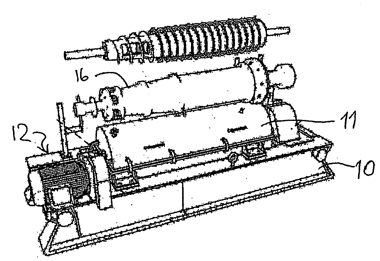
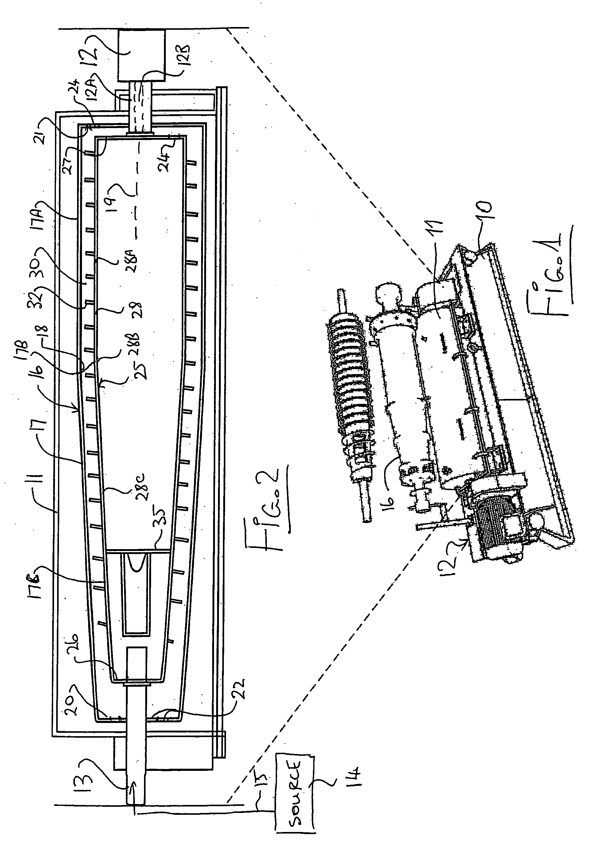
[0074] In FIG. 1 is shown schematically a centrifuge of the type with which the present invention is concerned. Centrifuges of this type have been manufactured for a number of years by the present assignee and details of the general construction of this centrifuge is well known to one skilled in the art.

[0075] The centrifuge generally comprises a base skid 10 on which is mounted on a fixed housing 11. The housing can be opened to access the interior of the housing and the elements therein. At one end of the housing is provided a motor and gear box arrangement schematically indicated at 12 which provides drive to the components inside the housing 11. At the other end of the housing is provided a feed duct 13 for supply of slurry from a source 14 through a duct 15.

[0076] Within the fixed housing 11 is provided an outer bowl 16 having a peripheral wall 17 with an inside surface 18. The bowl is mounted for rotation about a longitudinal axis 19 so that the inside surface of the periphe...


PUM


Abstract

A centrifuge of the type having an outer bowl and an inner rotor both of which are generally cylindrical and rotate in the same direction but at slightly different rates separates slurry fed into the interior of the rotor into solids and liquid. An auger flight on the outside surface of the rotor carries the solids along the annular channel between the outside of the rotor and the inside of the bowl. The slurry is fed into a chamber at one end of the rotor and through outlet holes in the sides of the rotor into the channel. An end plate of the chamber has a forwardly projecting domed central nose which extends into the flowing slurry. Transverse guide plates of the rotor act to engage the slurry and accelerate it into rotation with the rotor before escaping through the holes. The guide plates are shaped with curved angularly projecting ribs on the downstream side in front of the hole over which the slurry flows in a smooth path before exiting the hole.

Description

[0001] This invention relates to a centrifuge. BACKGROUND OF THE INVENTION [0002] Centrifuges have many different types and the present invention is concerned with the two phase centrifuge type which provides high speed horizontal decanting that separate solids from liquids. Centrifuges of this type have been manufactured by United Oilfield Inc., who are assignees of the present application for a number of years and each includes three primary parts which are the base or skid, the stainless steel case mounted on the skid and the rotating assembly consisting of the bowl, auger and gearbox which assembly is mounted in the stationary steel case on the skid. The auger is mounted in the bowl so that the bowl surrounds the auger and both are mounted for coaxial rotation about a longitudinal axis. The auger comprises generally a cylindrical body coaxial to the cylindrical bowl with an auger flight on its outer surface which has an edge close to the inside surface of the cylindrical bowl. [...

Claims


Application Information

Patent Timeline
IPC IPC(8): B04B1/20
CPCB04B2001/2033B04B1/20
Inventor LANTZ, EDWARD CARL
Owner LANTZ EDWARD CARL
Learn More