Steerable catheter assembly

a technology of steering device and assembly, which is applied in the direction of catheter, etc., can solve the problems of increasing the manufacturing cost of the steering device, sacrificing many advantages of the prior art steerable device, and increasing the weight of the product, so as to achieve maximum flexibility, maximum flexibility, and minimum flexibility

Inactive Publication Date: 2006-10-26
CREGANNA TECH
View PDF3 Cites 181 Cited by
  • Summary
  • Abstract
  • Description
  • Claims
  • Application Information

AI Technical Summary

Benefits of technology

[0021] Preferably, the outer shaft containing the lumen has a high column strength. The outer shaft is typically metallic. Preferably, the outer shaft is formed from stainless steel. Alternatively, the outer shaft may be formed from nitinol, a cobalt based alloy, or a suitable polymer. Preferably, the inner shaft has a high column strength. The inner shaft is typically metallic. Preferably, the inner shaft is formed from stainless steel. Alternatively, the inner shaft may be formed from nitinol, a cobalt based alloy, or a suitable polymer. An advantage of the catheter assembly of the present invention is that it provides the desirable properties of a hypotube, such as pushability, trackability, torqueability and kink resistance, while also providing the steerability normally associated with more complex pull wire systems. Another advantage of the catheter assembly of the present invention is that a working inner lumen may be provided.
[0029] According to yet another embodiment of the present invention, at least one spacer is disposed in the lumen of the outer shaft between the outer shaft and the inner shaft, such that an intermediate working lumen is established therebetween. An advantage of this arrangement is that a second working lumen is thus available for use during the surgical procedure. The second working lumen may be used for delivery of instruments to a site within the body, delivery of contrast media or for inflation of a balloon catheter. An additional advantage is that concentricity between the inner and outer shafts is maintained.
[0030] According to another aspect of the invention there is provided a steerable catheter assembly, comprising an elongate outer shaft having a lumen therethrough and having a proximal end and a distal end; an elongate inner shaft coaxially disposed within the lumen of the outer shaft and having a proximal end and a distal end; and characterised in that the distal portion of the inner shaft is capable of bending in a pre-determined bend plane only, and the distal portion of the outer shaft is capable of bending in a pre-determined bend plane only, and in an aligned configuration, the bend plane of the distal portion of the inner shaft is substantially aligned with the bend plane of the distal portion of the outer shaft, such that a distal end of the catheter assembly is capable of bending in the pre-determined bend plane with a maximum flexibility; and the inner shaft and the outer shaft are rotatable relative to one another out of the aligned configuration so that the bend plane of the distal portion of the inner shaft is moved out of alignment with the bend plane of the distal portion of the outer shaft to vary the flexibility of the distal end of the catheter assembly between the maximum flexibility and a minimum flexibility.
[0032] An advantage of this arrangement is that when inserting a device in a body lumen of a patient, such as for example, a pacemaker lead, is that the catheter assembly may be stiffened when it is required to push the device through a blockage, and may be made more flexible when it is required to navigate through the tortuous pathways of the vasculature. Prior art systems require separate stiff and flexible styluses to be used, wherein each stylus is alternately inserted and withdrawn from the body as required.

Problems solved by technology

Prior art steerable devices have often sacrificed many of the advantages of non-steerable delivery devices such as hypotubes.
This has the disadvantage of increasing manufacturing costs of the steerable device.
It also has the disadvantage of adding weight to the product and increasing the overall profile of the device, thus making the procedure more uncomfortable for the patient.
In addition, relatively complex handles are required in order to control tension in the pull wire.
These are often bulky, with poor ergonomics and can be costly to manufacture.
Furthermore, the pull wires are used under tension, and there is thus a possibility of breakage of the pull wires under tension during use.
A further disadvantage with this type of catheter is that the tip of the catheter may only be deflected in a single plane.
This restriction limits the effectiveness of this type of catheter in reaching many of the desired treatment sites.
Due to the fact that the material yield strength, and thus the column strength of a polymer tube is significantly lower than that of a steel tube, use of such extrusions is likely to result in a delivery device with lower pushability and torqueability than hypotubes.
However, the resulting device still does not perform as well as a metal hypotube.
This type of arrangement may also lead to ‘springback’ in the device.
This can make small, accurate movements difficult to achieve.
However, including additional pull wires in the assembly has the effect of compounding the original problems of large profile devices, high manufacturing costs and more complex handles.
Since the capability to deliver a device or a treatment through the lumen is now lost, a second device may be necessary to carry out this function.
This results in longer surgical procedures, increased material cost per procedure and increased risk to the patient.
Another disadvantage of the loss of the working lumen is that the surgeon can no longer track the catheter over a guidewire, which is a widespread practice in percutaneous, minimally invasive procedures.
One disadvantage of this steerable catheter is that longitudinal movement of one shaft relative to the other is required.
For this reason, the catheter device may not be suitable for placing a stent or balloon within a body vessel of a patient.
Furthermore, as the tip of the device is flexible, pushing a rigid device such as an ablation catheter through the inner member would be likely to force the flexible tip to straighten.

Method used


Image

  • Steerable catheter assembly
  • Steerable catheter assembly
  • Steerable catheter assembly

Examples


first embodiment

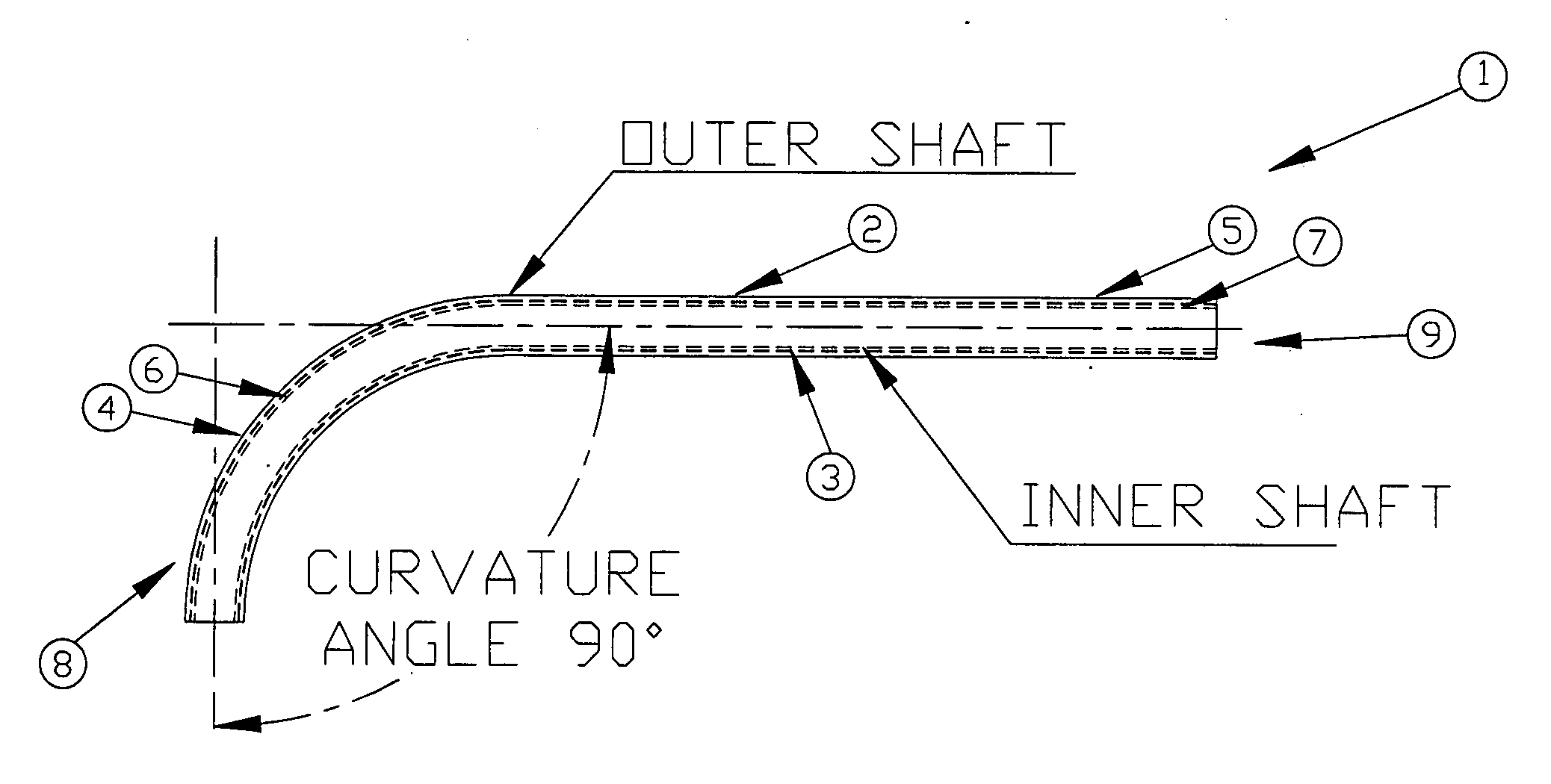
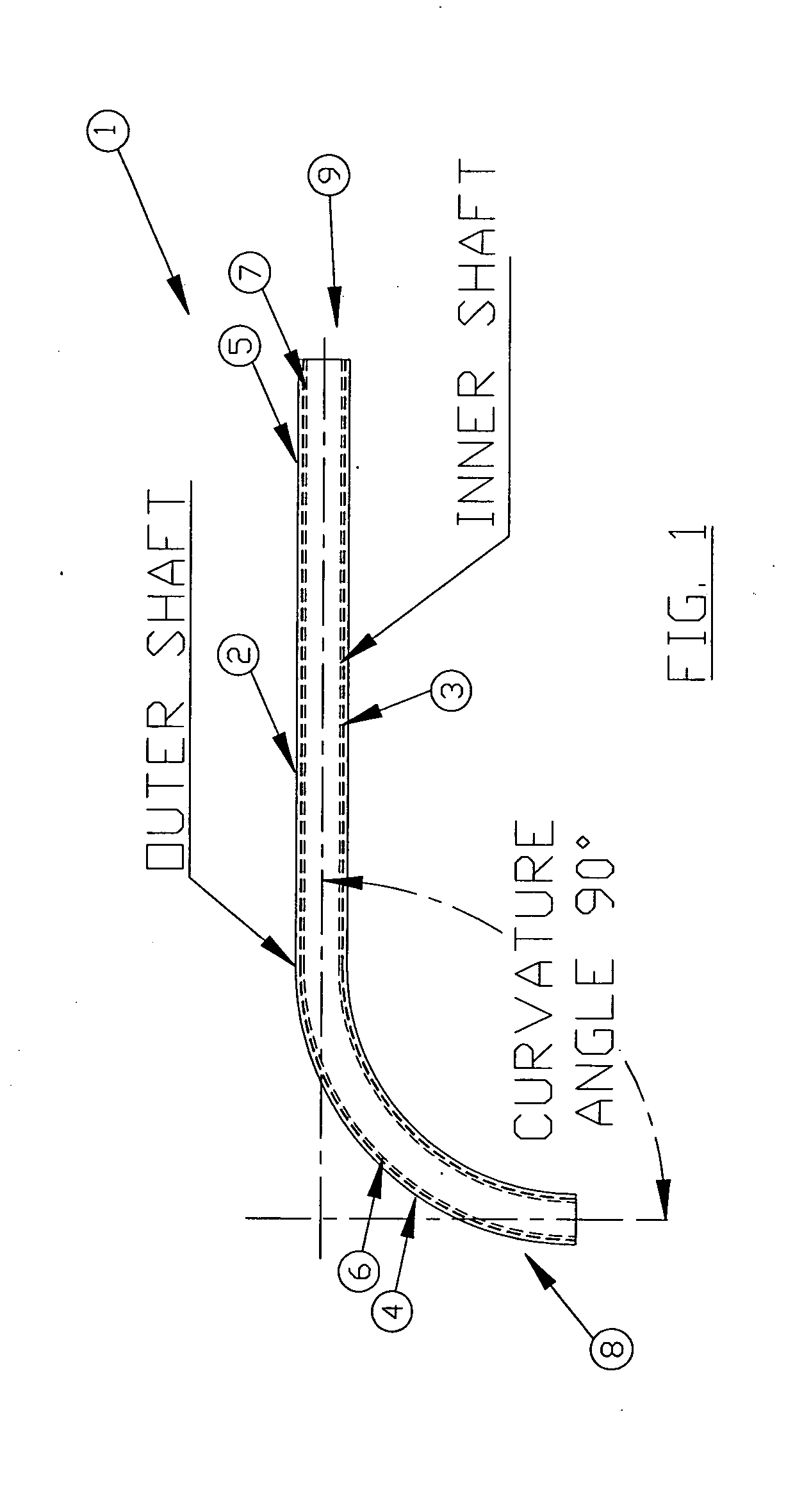
[0053] the steerable catheter assembly of the present invention is shown in FIGS. 1 and 2. The catheter assembly 1 comprises a stainless steel outer shaft 2, having a lumen extending therethrough and a stainless steel inner shaft 3, having a lumen extending therethrough. Each of the shafts is of thin-walled construction. In alternative embodiments, the shafts may be formed from other metals, or from suitable plastics. The inner shaft is coaxially disposed within the outer shaft.

[0054] The outer shaft 2 is formed with a bend (or curvature) of approximately 90 degrees at a distal portion 4. The bend or curvature may be formed, for example, by heat treatment of the shaft. In an ‘at rest’ or unstressed position, the outer shaft distal end 4 will be disposed at an angle of approximately 90 degrees to the proximal end 5 of the shaft. The bend or curvature is such that if the outer shaft is manually straightened, the shaft will automatically return to its unstressed position on release. Th...

second embodiment

[0060] the steerable catheter assembly of the present invention is shown in FIG. 9. The inner shaft 3 is formed with a curvature of approximately 90 degrees at a distal end 6. This curvature may be formed, for example, by heat treatment of the shaft 3 or by use of shape memory material as described above with reference to FIG. 3. The outer shaft 2 is not pre-formed with a bend or curvature but has had material removed at a distal portion 4 to form slots 10 on one side of the shaft 2. The outer shaft is formed from a material such as stainless steel and the slots 10 allow the outer shaft 2 to bend in one direction only. The slots render the shaft 2 sufficiently flexible to allow it to adopt the same shape as the inner shaft 3. In the ‘at rest’ position, the catheter assembly distal end 8 is therefore disposed at an angle of approximately 90 degrees to the catheter assembly proximal end 9. In this embodiment, the outer shaft 2 is clamped at its proximal end 5 so that it cannot rotate,...

third embodiment

[0061] A third embodiment is shown in FIG. 10. In this embodiment, the outer shaft 2 is formed with a curvature of approximately 90 degrees at its distal end 4 as described above with reference to FIGS. 1 to 3. The inner shaft 3 is not formed with a bend or curvature but has had material removed at a distal portion 4 to form slots 10 on one side of the shaft 2. The inner shaft 3 is formed from a material such as stainless steel and the slots 10 allow the inner shaft 3 to bend in one direction only. The slots render the shaft 3 sufficiently flexible to allow it to adopt the same shape as the outer shaft 2. In the ‘at rest’ position, the catheter assembly distal end 8 is therefore disposed at an angle of approximately 90 degrees to the catheter assembly proximal end 9. In this embodiment, the inner shaft 3 is clamped at its proximal end 7 so that it cannot rotate, whereas the outer shaft 2 is freely rotatable. When the outer shaft is rotated relative to the inner shaft, the inner shaf...


PUM


Abstract

The present invention relates to a steerable catheter assembly, comprising an elongate outer shaft having a lumen therethrough and having a proximal end and a distal end; an elongate inner shaft coaxially disposed within the lumen of the outer shaft and having a proximal end and a distal end; and characterised in that at least one of the inner shaft and the outer shaft is formed with a curvature at a distal portion, such that in an aligned configuration, a distal end of the catheter assembly is disposed at a maximum deflection angle α to a longitudinal axis of the catheter assembly; and the inner shaft and the outer shaft are rotatable relative to one another out of the aligned configuration such that each shaft exerts a deflection force on the other shaft to deflect the distal end of the catheter assembly between α and 0 degrees to the longitudinal axis of the catheter assembly.

Description

FIELD OF THE INVENTION [0001] The invention relates to steerable catheters for use in minimally invasive surgical procedures. BACKGROUND TO THE INVENTION [0002] Catheters for insertion into bodily lumens, e.g. intravascular catheters and the like are well known in the art. Catheters typically employ elongate flexible tubes made from a synthetic plastics material or from stainless steel. Desirable characteristics of catheter tubing include “pushability”, that is the ability to transfer forces from the proximal to the distal end of the catheter. It is also an advantage for the catheter to have good “trackability”, i.e. to be sufficiently flexible as to be capable of navigating tortuous paths within a body lumen without kinking. It is also desirable for the catheter to have good “torqueability”, as manipulation of a device within a body lumen often requires small precise amounts of torque to be applied. [0003] Non-steerable delivery devices such as hypotubes are widely used for deliver...

Claims


Application Information

Patent Timeline
Patent Type & Authority Applications(United States)
IPC IPC(8): A61M25/00
CPCA61M25/0138A61M2025/0063A61M25/0152A61M25/0147
Inventor CORCORAN, NEILO'REILLY, DERMOT
Owner CREGANNA TECH
Why Eureka
Try Eureka