Bi-directional fixating transvertebral body screws, zero-profile horizontal intervertebral miniplates, expansile intervertebral body fusion devices, and posterior motion-calibrating interarticulating joint stapling device for spinal fusion

a transvertebral body and screw technology, applied in the direction of surgical staples, ligaments, prostheses, etc., can solve the problems of pseudoarthrose, prolonged recovery, and excessive blood loss

Inactive Publication Date: 2006-10-26
MOSKOWITZ NATHAN C
View PDF47 Cites 149 Cited by
  • Summary
  • Abstract
  • Description
  • Claims
  • Application Information

AI Technical Summary

Problems solved by technology

Because of the poor blood supply of the transverse processes, issues still remained with pseudoarthroses.
Complications of pedicle screw placement include duration of procedure, significant tissue dissection and muscle retraction, misplaced screws with neural and/or vascular injury, excessive blood loss, need for transfusions, prolonged recovery, incomplete return to work, excess rigidity leading to adjacent segmental disease requiring further fusions and re-operations.
Complications of all current interbody fu...

Method used


Image

  • Bi-directional fixating transvertebral body screws, zero-profile horizontal intervertebral miniplates, expansile intervertebral body fusion devices, and posterior motion-calibrating interarticulating joint stapling device for spinal fusion
  • Bi-directional fixating transvertebral body screws, zero-profile horizontal intervertebral miniplates, expansile intervertebral body fusion devices, and posterior motion-calibrating interarticulating joint stapling device for spinal fusion
  • Bi-directional fixating transvertebral body screws, zero-profile horizontal intervertebral miniplates, expansile intervertebral body fusion devices, and posterior motion-calibrating interarticulating joint stapling device for spinal fusion

Examples


Embodiment Construction

1. The Medical Device

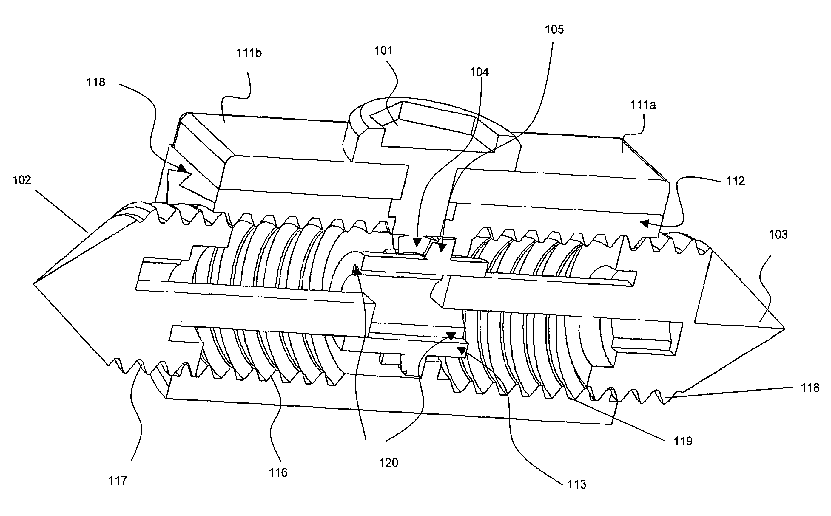
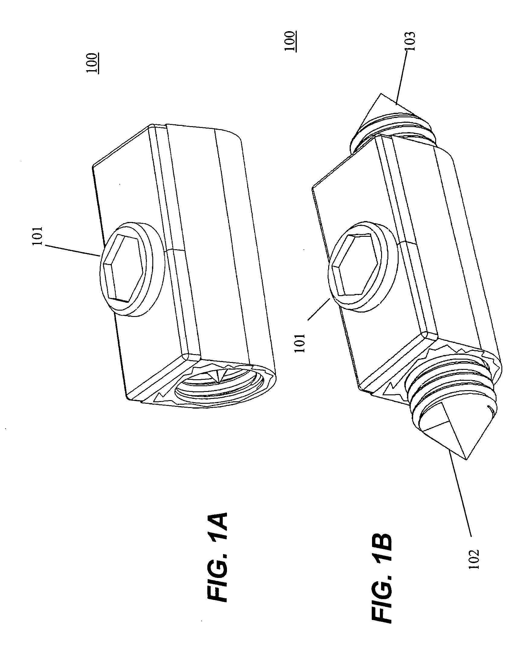
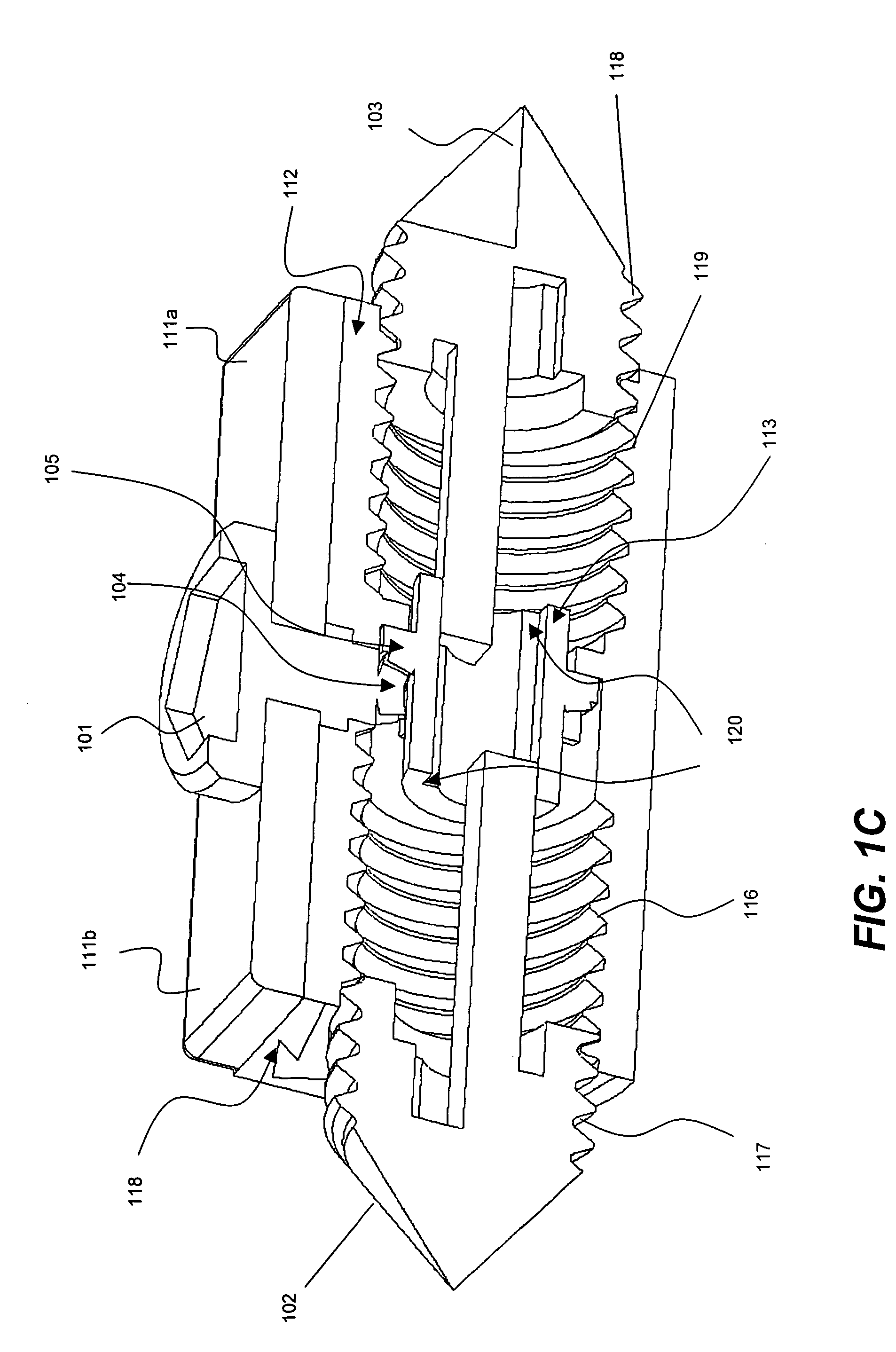
[0031] Referring to FIGS. 1A-D the above described problem can be solved in the cervical, thoracic and lumbar spine by insertion into the denuded intervertebral disc space an expansile bi-directional fixating transvertebral (BDFT) screw 100 or screws.

[0032]FIGS. 1A and 1B illustrate three-dimensional views of the screw 100 in closed and opened positions, respectively, upon its insertion into the intervertebral disc space. The screw 100 is self-drilling. The mechanism of its action entails the turning of a midline drive screw 100 / pinion 104 in a clock-wise direction. This motion is bi-directionally translated via an interposing gear mechanism 105 enabling the simultaneous outward movement of left and right handed screws 102, 103 in equal and opposite directions. When the drive screw 101 and its accompanying drive screw shaft are turned clock-wise, the driving pinion 104 is likewise rotated. This motion is then translated to the driven gear 105 which is interpo...


PUM

PropertyMeasurementUnit
Forceaaaaaaaaaa
Diameteraaaaaaaaaa
Distanceaaaaaaaaaa

Abstract

An apparatus and method for joining members together using a self-drilling screw apparatus or stapling apparatus are disclosed. The screw apparatus includes a shell and first and second first screw members having tapered ends and threaded bodies that are disposed within the shell. A drive mechanism rotatably drives the first and second screw members from the shell in opposite directions and causes the screw members to embed themselves in the members to be joined. The screw apparatus can be used to join members such as bones, portions of the spinal column, vertebral bodies, wood, building materials, metals, masonry, or plastics. The stapling apparatus includes first and second lever arms rotatably joined together at a fulcrum, and the lever arms rotate in opposite directions. First and second cartridges are disposed at the ends of the lever arms. Each cartridge is capable of holding a staple including a bracket, a nail member and an alignment slot. When the ends of the lever arms are rotated towards each other the staples from the cartridges are interlocked. The staples can be also be used to join members such as bones, portions of the spinal column, or vertebral bodies.

Description

[0001] The present application claims the benefit of Provisional Application No. 60 / 670,231, filed on Apr. 12, 2005, the entire contents of which is incorporated herein by reference.FIELD OF INVENTION [0002] The present invention relates to bi-directional fixating transvertebral (BDFT) screws which can be used to supplement other intervertebral spacers and / or bone fusion materials. BDFT screws can be incorporated into anterior and / or posterior cervical and lumbosacral novel zero-profile horizontal and triangular intervertebral mini-plates. In addition BDFT screws can be incorporated into two dimensional, expansile intervertebral body fusion devices (IBFDs) transforming them into stand-alone posteriorly and / or anteriorly placed cervical, thoracic and lumbar spinal fusion devices. In the lumbosacral and thoracic spine BDFT screws may obviate the need for supplemental pedicle screw fixation. In the cervical spine it obviates the need for supplemental vertically oriented anterior platin...

Claims


Application Information

Patent Timeline
IPC IPC(8): A61B17/58
CPCA61B17/0642A61F2310/00796A61B17/0682A61B17/7064A61B2017/0648A61F2/4455A61F2002/2835A61F2002/3052A61F2002/30525A61F2002/30579A61F2002/30841A61F2002/3085A61F2002/448A61F2220/0025A61B17/0643
Inventor MOSKOWITZ, MOSHEH T.MOSKOWITZ, NATHAN C.
Owner MOSKOWITZ NATHAN C
Why Eureka
Try Eureka