Monitoring system

a monitoring system and monitoring technology, applied in the direction of liquid/fluent solid measurement, machine/engine, process and machine control, etc., can solve the problems of not being able to monitor in a form, monitoring is not ongoing, and considerable time may be needed in analysis

Inactive Publication Date: 2006-10-26
HYDRO AUDITING SYST PTY LTD
View PDF9 Cites 32 Cited by
  • Summary
  • Abstract
  • Description
  • Claims
  • Application Information

AI Technical Summary

Problems solved by technology

One major problem with current monitoring techniques to determine the state of fluid used in these environments is that the monitoring is not ongoing and is generally only conducted on an ad hoc or periodical basis.
Whilst some systems do provide ongoing monitoring, the problem with these systems is that the results of monitoring are not in a form which can be easily inspected and interpreted, and therefore considerable time may be needed in analysis in order to determine whether a problem does exist.
Obviously, once the analysis has been completed and the time period passed, the damage caused by the inappropriate conditions may have already occurred and not be reversible.
Thus, whilst testing may show that the water is suitable for the intended purpose, it may be that the characteristics of the water has changed significantly between measurement times, and whilst was within satisfactory limits at the measurement times, was not at these levels during various periods between measurements.
Thus, the water may have acquired characteristics which make the water unsuitable for discharge to the environment in the case of trade and industrial waste water plants, or in which legionnaire can flourish in the case of air conditioning cooling towers.

Method used


Image

  • Monitoring system
  • Monitoring system
  • Monitoring system

Examples


Embodiment Construction

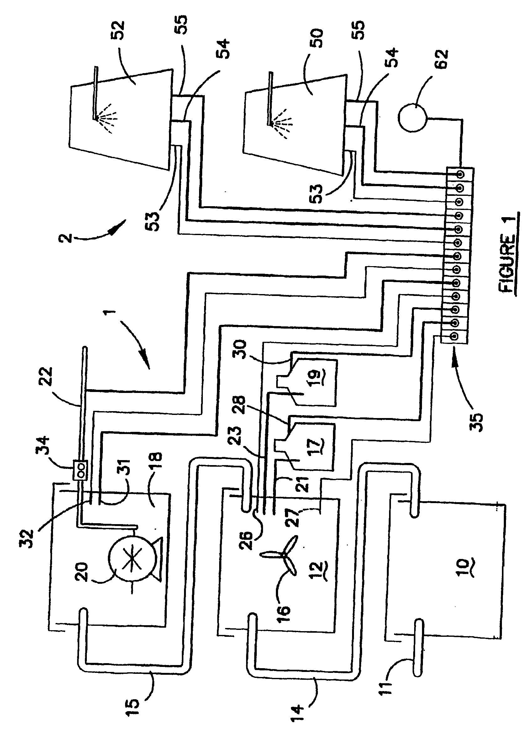
[0096]FIG. 1 is a view of both a trade / industrial waste water plant 1 and a cooling tower installation 2 for an air conditioning system of a building. However, it should be understood that the present invention is applicable to monitoring only either the waste water plant or the cooling tower installation on its own, or if the waste water plant and the cooling tower installation are both utilised at a particular site, both the plant and installation could be monitored concurrently by the same system.

[0097] The waste water plant comprising a collection tank 10 which collects waste water from a trade or industrial site (not shown) at inlet 11. Waste water from the collection tank 10 is gravity fed to a mixing tank 12 via a pipe or conduit 14. The mixing tank 12 includes a mixing vane 16. An acid reservoir 17 and an alkaline reservoir 19 are provided for supplying acid solution and alkaline solution respectively to the mixing tank 12 to adjust the pH level of the waste water in the mi...


PUM

PropertyMeasurementUnit
timeaaaaaaaaaa
pHaaaaaaaaaa
temperatureaaaaaaaaaa

Abstract

A monitoring system for monitoring fluid used in an environment such as a trade / industrial waste plant or air conditioning cooling tower installation is disclosed. The system includes sensors (26 to 34, 53 to 55) for sensing parameters of the fluid, a remote monitoring system (40) for receiving signals indicative of the measured parameters from the sensors and for applying rules to the signals to determine whether the signals meet predetermined criteria so that an event indication can be generated if the predetermined criteria are not met. The system (40) includes a processor (41) and a memory (42). The system (40) is connected to a central station (72) by a communication link (74). The central station (72) includes a server (80) and data store (82) which are connected to the Internet so the data can be interrogated by a user via a PC (86). The system also generates an audible or visual alarm (62) or forwards a message to authorised personnel via SMS message to a mobile telephone (87) or by e-mail in the case of an event condition being generated. A user is able to log onto the system and interrogate data retained in the system relating to the user's sites to determine the operating parameters of the system and also to determine problems if an event indication is established.

Description

FIELD OF THE INVENTION [0001] This invention relates to a monitoring system for monitoring environments such as trade / industrial waste water plants or cooling towers used in air conditioning systems for buildings. BACKGROUND ART [0002] Many environments exist in which various types of fluids need to be monitored to determine particular characteristics of the fluid to, for example, determine whether the fluids are suitable for discharge to drain or whether the fluids are of such a character that they are suitable for the intended purpose and do not show signs of becoming contaminated. [0003] Two such environments in which monitoring of fluids is required are trade / industrial waste water plants in which waste water is collected, processed and then discharged to drain, and also water used in cooling towers used in air conditioning systems for buildings and like premises. [0004] Waste water plants generally receive waste water from a variety of sources and the water is processed to ensu...

Claims


Application Information

Patent Timeline
Patent Type & Authority Applications(United States)
IPC IPC(8): G06F19/00C02F1/00C02F1/66F28F27/00G05B23/02G05D9/12G05D21/02
CPCC02F1/008C02F1/66C02F2209/006C02F2209/008C02F2209/02G05D21/02C02F2209/40C02F2209/42F28F27/003G05D9/12C02F2209/06Y02W10/37
Inventor CARTER, PETER JOHN
Owner HYDRO AUDITING SYST PTY LTD
Why Eureka
Try Eureka