Methods and systems for monitoring tumor burden

a technology of computed tomography and tumor burden, applied in the field of methods and systems for monitoring tumor burden, can solve the problems of limited contrast, difficult to identify tumor boundaries, limited visual contrast of liver lesions on ct images,

Active Publication Date: 2006-10-26
GENERAL ELECTRIC CO
View PDF19 Cites 33 Cited by
  • Summary
  • Abstract
  • Description
  • Claims
  • Application Information

AI Technical Summary

Benefits of technology

[0007] In another embodiment, an imaging system is provided. The imaging system includes an image acquisition portion for acquiring image data, a controller configured to control the image acquisition portion, and a processor configured to quantify a selected attribute of an image volume and monitor changes of the selected attribute. The processor is further programmed to receive an image dataset for a volume of interest from at least one of an X-ray modality, a CT modality, an ultrasound modality, a magnetic resonance imaging (MRI) modality, a positron emission tomography (PET) modality, a nuclear medicine modality, an optical modality, and a combination of modalities, to process the dataset for a selected attribute based at least on one of shape and texture to obtain a plurality of responses, and to compute an index of an aggregate of a plurality of obtained responses.

Problems solved by technology

The visual contrast of liver lesions on CT images is limiting to the human eye.
Magnetic Resonance Imaging (MRI) and Positron Emission Tomography (PET) imaging have proven superior to CT for visualizing liver tumors, but contrast remains limited.
This can be problematic in patients with “bulky disease” (meaning that the tumor burden is an overestimate of the actual presence of cancer cells) if the cancer remises, but the relative size of the tissue mass does not change.
Under some circumstances, a tumor can have limited contrast and / or be ill-defined, meaning that the boundaries of the tumor are difficult to identify.
However, when there are multiple lesions, it is extremely time consuming to identify and track each individual lesion.
However, even tracking TTB over the course of a treatment regime may also require a difficult and time consuming procedure.

Method used


Image

  • Methods and systems for monitoring tumor burden
  • Methods and systems for monitoring tumor burden
  • Methods and systems for monitoring tumor burden

Examples


Embodiment Construction

[0021] As used herein, an element or step recited in the singular and proceeded with the word “a” or “an” should be understood as not excluding plural said elements or steps, unless such exclusion is explicitly recited. Furthermore, references to “one embodiment” of the present invention are not intended to be interpreted as excluding the existence of additional embodiments that also incorporate the recited features.

[0022] Also as used herein, the phrase “reconstructing an image” is not intended to exclude embodiments of the present invention in which data representing an image is generated but a viewable image is not. Therefore, as used herein the term, “image,” broadly refers to both viewable images and data representing a viewable image. However, many embodiments generate (or are configured to generate) at least one viewable image.

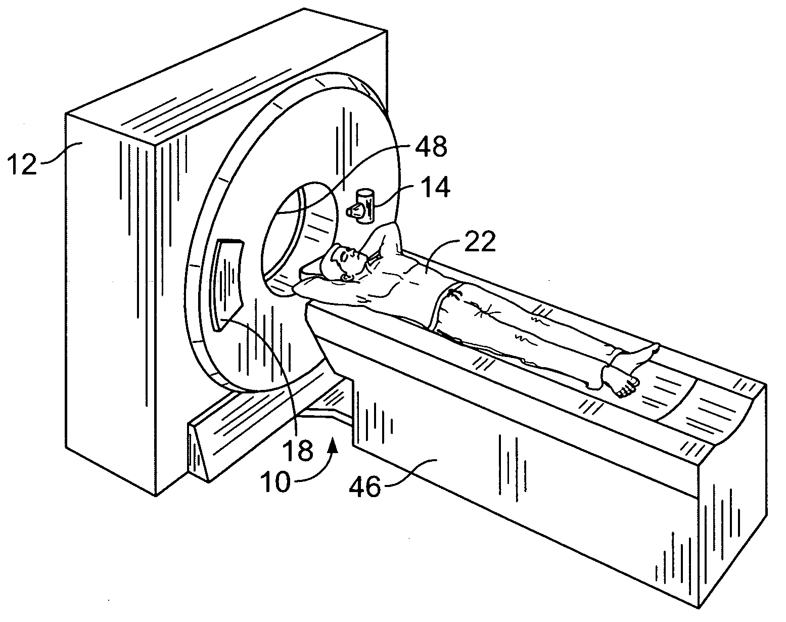
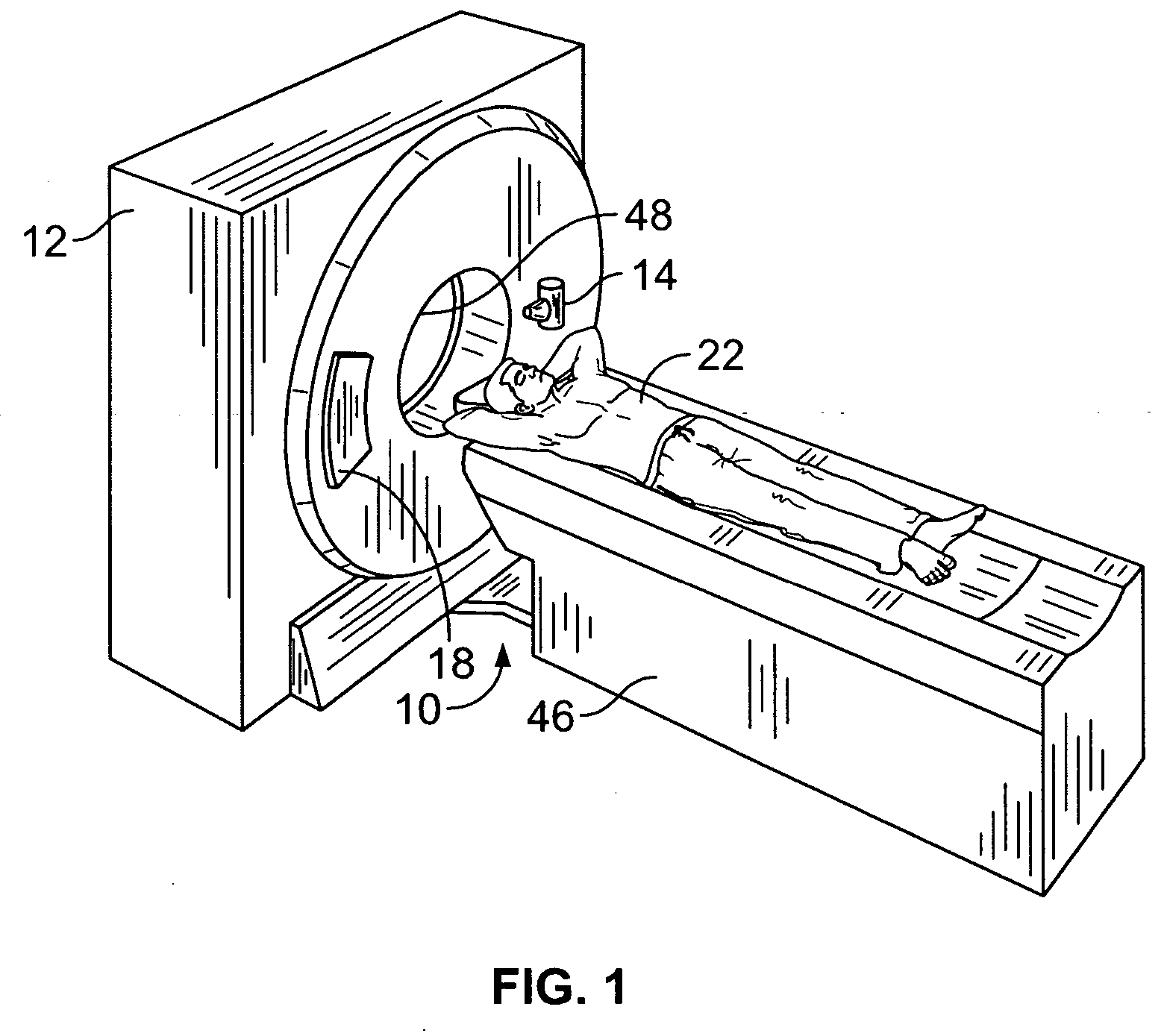
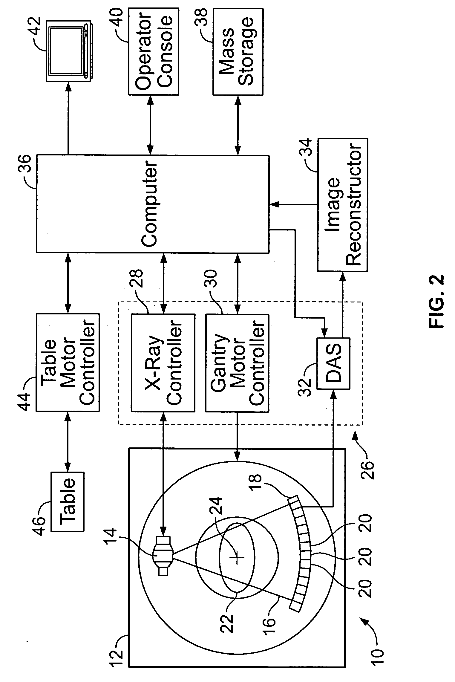
[0023]FIG. 1 is a pictorial view of a multi slice volumetric CT imaging system 10. FIG. 2 is a block schematic diagram of system 10 illustrated in FI...


PUM


Abstract

Methods and systems for quantification of a selected attribute of an image volume are provided. The system is configured to receive an image dataset for a volume of interest, process the dataset for a selected attribute based at least on one of shape and texture to obtain a plurality of responses, and compute an index of an aggregate of a plurality of obtained responses.

Description

BACKGROUND OF THE INVENTION [0001] This invention relates generally to computed tomography (CT) imaging and more particularly, to quantification of a selected attribute of an image volume and monitoring changes of the selected attribute in a patient. [0002] Visualization of anatomical data acquired by imaging devices generating 3D data is typically handled by volume rendering of its intensity and / or density values (Hounsfield Units (HU) in the case of Computed Tomography for instance). Many clinical applications are based on 3D visualization of the volumetric data that may include, but are not limited to, detection and sizing of lung nodules, quantification of vessel curvature, diameter and tone, cardiac vascular and function applications, and navigation of the colon for detection of polyps. These applications rely on the absolute values of the image data (intensity, density (HU), uptake (standard uptake values (SUV)), and other material properties associated with medical imaging to...

Claims


Application Information

Patent Timeline
Patent Type & Authority Applications(United States)
IPC IPC(8): G06F7/00A61B5/055A61B6/03A61B8/08
CPCG06K9/4609G06T7/604G06T7/0012G06T7/64G06V10/443
Inventor PIACSEK, KELLY LYNNSIROHEY, SAAD AHMEDFERRANT, MATTHIEU DENISAVINASH, GOPAL B.
Owner GENERAL ELECTRIC CO
Why Eureka
Try Eureka