
Particulate sampling system having flow check device

a sampling system and flow check technology, applied in the field of particle sampling system, can solve the problem that the method and apparatus of the '788 patent may not perform a self-check step to determine the accuracy of the apparatus

Active Publication Date: 2006-11-02
CATERPILLAR INC
View PDF23 Cites 23 Cited by
  • Summary
  • Abstract
  • Description
  • Claims
  • Application Information

AI Technical Summary

Benefits of technology

[0007] In one aspect, the present disclosure may be directed to a particulate sampling system. The particulate sampling system may include an exhaust sampling unit configured to receive exhaust, a dilution flow assembly located upstream of the exhaust sampling unit and configured to supply dilution air to the exhaust sampling unit, and a total flow assembly located downstream of the exhaust sampling unit and configured to receive dilution air and exhaust. The particulate sampling system may also include a flow regulation assembly configured to control flow rates in the dilution flow assembly and the total flow assembly, and a flow check assembly configured to measure the accuracy of the flow regulation assembly.
[0008] In another aspect, the present disclosure may be directed to a method for determining the concentration of particles in an exhaust gas. The method may include passing exhaust to an exhaust sampling unit, and passing dilution air through a dilution flow assembly at a first predetermined flow rate using a flow regulation assembly. The method may also include passing diluted exhaust through a total flow assembly at a second predetermined flow rate using the flow regulation assembly, and comparing the first predetermined flow rate to the second predetermined flow rate to determine an exhaust flow rate. The method may further include selectively bypassing the dilution air around the exhaust sampling unit to the total flow assembly, and allowing air to flow to the total flow assembly while bypassing. The method may also include measuring an air flow rate, and comparing the determined exhaust flow rate and the measured air flow rate to check the accuracy of the determined exhaust flow rate.
[0009] In yet another aspect, the present disclosure may be directed to a an engine test cell. The engine test cell may include an internal combustion engine and an air supply unit configured to provide air to the internal combustion engine during testing of the internal combustion engine in the engine test cell. The engine test cell may also include an engine air intake operatively connected to the internal combustion engine and at least one conduit to channel air from the air supply unit to the engine air intake. The engine test cell may further include an engine stack to channel exhaust away from the internal combustion engine and a particulate sampling system operatively connected to the engine stack. The particulate sampling system may include an exhaust sampling unit configured to receive exhaust and a dilution flow assembly located upstream of the exhaust sampling unit and configured to supply dilution air to the exhaust sampling unit. The particulate sampling system may also include a total flow assembly located downstream of the exhaust sampling unit and configured to receive dilution air and exhaust. The particulate sampling system may further include a flow regulation assembly configured to control flow rates in the dilution flow assembly and the total flow assembly, and a flow check assembly configured to measure the accuracy of the flow regulation assembly.

Problems solved by technology

The method and apparatus of the '788 patent may not perform a self-check step to determine the accuracy of the apparatus.

Method used


Image

  • Particulate sampling system having flow check device
  • Particulate sampling system having flow check device
  • Particulate sampling system having flow check device

Examples


Embodiment Construction

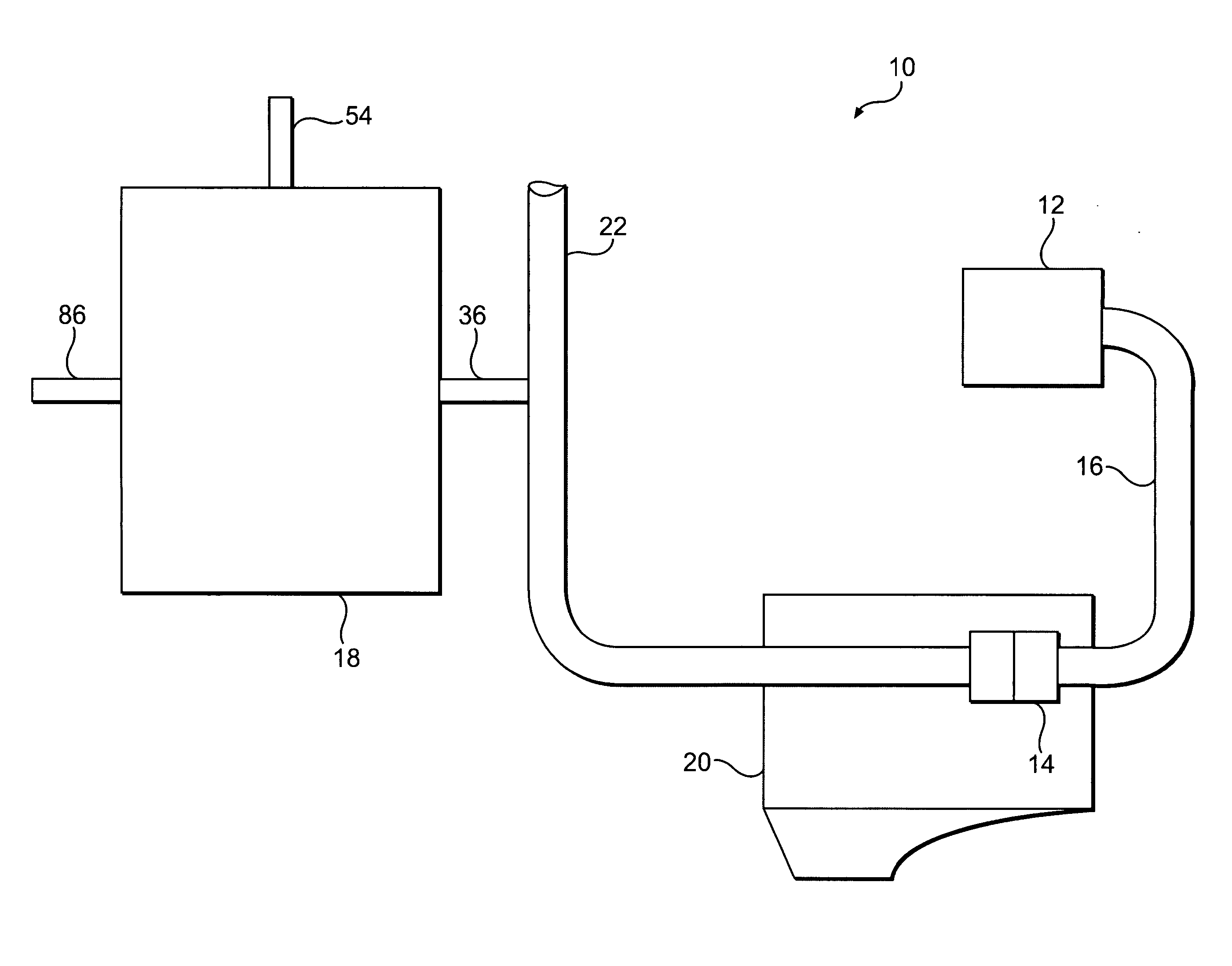
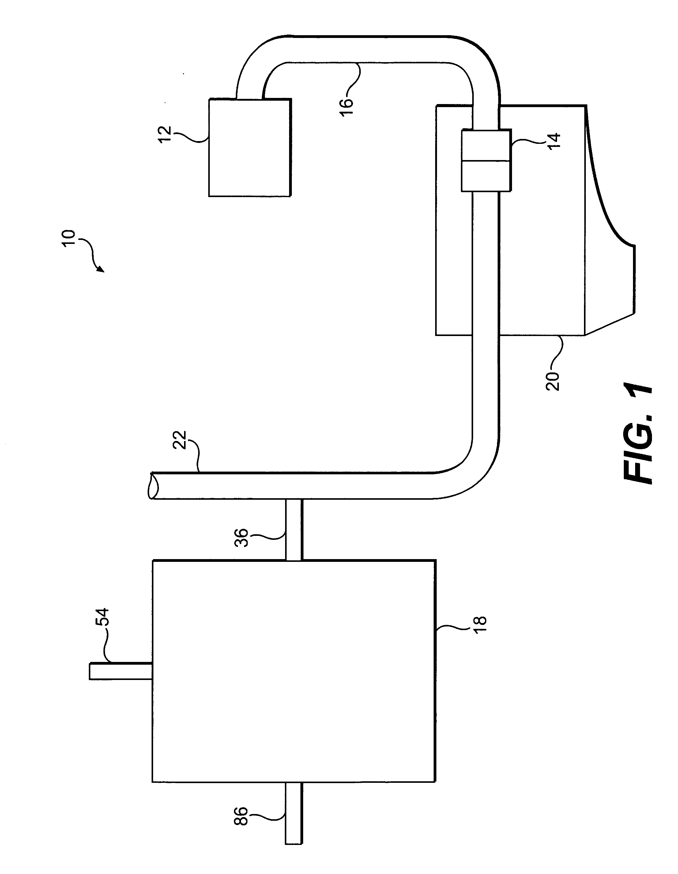
[0012]FIG. 1 illustrates an engine test cell 10 according to an exemplary disclosed embodiment. This engine test cell 10 may be used to test emissions of, for example, diesel engines, gasoline engines, and gaseous fuel-powered engines. Engine test cell 10 may include an air supply unit 12, an engine air intake 14, one or more conduits 16 between the air supply unit 12 and engine air intake 14, an engine 20, and a particulate sampling system 18. Engine 20 may expel exhaust through an engine stack 22.

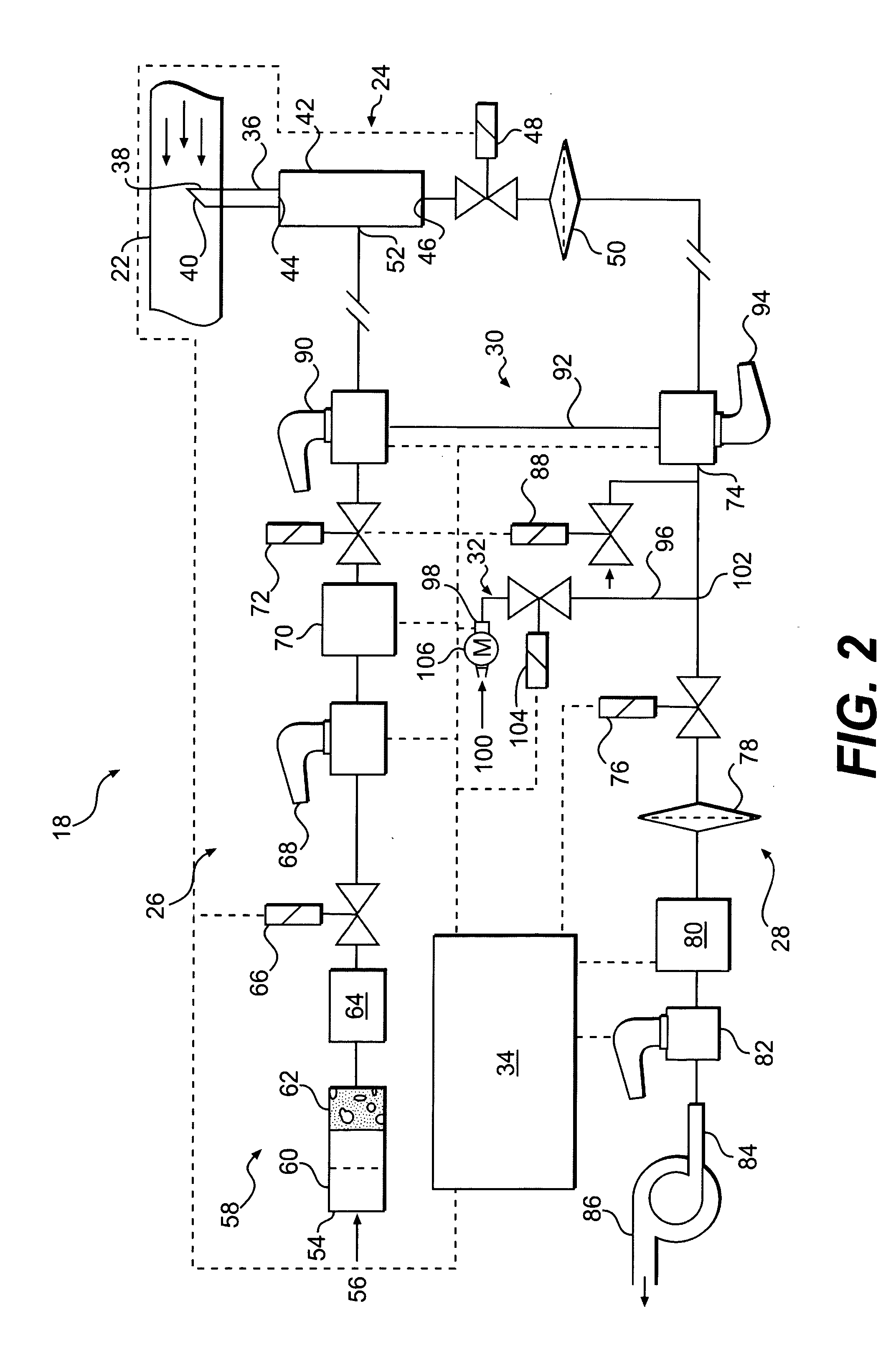
[0013] As illustrated in FIG. 1, engine test cell 10 may include particulate sampling system 18 to assist in quantifying one or more parameters of engine exhaust. For example, in response to receiving exhaust, particulate sampling system 18 may determine flow rate, concentration of particulate matter, and other values of the exhaust which may be recorded and used for emissions testing. Particulate sampling system 18 and its components are illustrated in FIG. 2. In one embodiment, particu...


PUM

PropertyMeasurementUnit
flow ratesaaaaaaaaaa
air flow rateaaaaaaaaaa
flow rateaaaaaaaaaa

Abstract

A particulate sampling system is disclosed. The particulate sampling system may include an exhaust sampling unit and a dilution flow assembly to supply dilution air to the exhaust sampling unit. The particulate sampling system may also include a total flow assembly to receive dilution air and exhaust. The particulate sampling system may further include a flow regulation assembly configured to control flow rates in the dilution flow assembly and the total flow assembly. The particulate sampling system may also include a flow check assembly configured to measure the accuracy of the flow regulation assembly.

Description

TECHNICAL FIELD [0001] The present disclosure relates to a particulate sampling system, and more particularly, to a particulate sampling system having a flow check assembly. BACKGROUND [0002] Engines, including diesel engines, gasoline engines, natural gas engines, and other engines known in the art, may exhaust a complex mixture of air pollutants. The air pollutants may be composed of gaseous and solid material, which may include particulate matter. Particulate matter may include unburned carbon particles, which are also called soot. [0003] Due to increased attention on the environment, exhaust emission standards have become more stringent. The amount of particulates emitted from an engine may be regulated depending on the type of engine, size of engine, and / or class of engine. One method that has been implemented by engine manufacturers to ensure compliance with exhaust emission standards has been to periodically sample the emissions of engines within test cells. [0004] One such m...

Claims


Application Information

Patent Timeline
Patent Type & Authority Applications(United States)
IPC IPC(8): G01M15/10G01N1/24
CPCG01M15/102
Inventor GRAZE, RUSSELL ROBERT JR.RANDALL, JERRY KIRK
Owner CATERPILLAR INC
Learn More