Camera module

a camera module and camera technology, applied in the field of camera modules, can solve the problems of deteriorating the function of the optical filter, affecting the image quality of the camera module, and unable to remove extraneous matter completely,

Inactive Publication Date: 2006-11-02
FUJITSU SEMICON LTD
View PDF9 Cites 35 Cited by
  • Summary
  • Abstract
  • Description
  • Claims
  • Application Information

AI Technical Summary

Benefits of technology

[0020] It is a general object of the present invention to provide an improved and useful camera module in which the above-mentioned problems are eliminated.

Problems solved by technology

The optical filter after cutting is cleaned by air blow or the like since an optical filter function may be deteriorated if it is washed by water or liquid.
However, according to air blow, extraneous matter cannot be removed completely.
In such a case, there is a problem in that quality of the image obtained by the camera module is deteriorated.
In the cameral module of the above-mentioned structure, it is necessary to make a thickness of the plastic molded part (that is, a distance between the image pickup lens and the imaging element) to be a predetermined dimension so as to acquire a focal distance of the image pickup lens, and, thus, there exists a wasted space in the plastic molded part.
There may be a problem generated due to influences of such an electromagnetic field in that a noise is generated in the image signal output from the imaging element, thereby deteriorating the image.

Method used


Image

  • Camera module
  • Camera module
  • Camera module

Examples


first embodiment

[0059] First, a description will be given, with reference to FIG. 1, of the present invention.

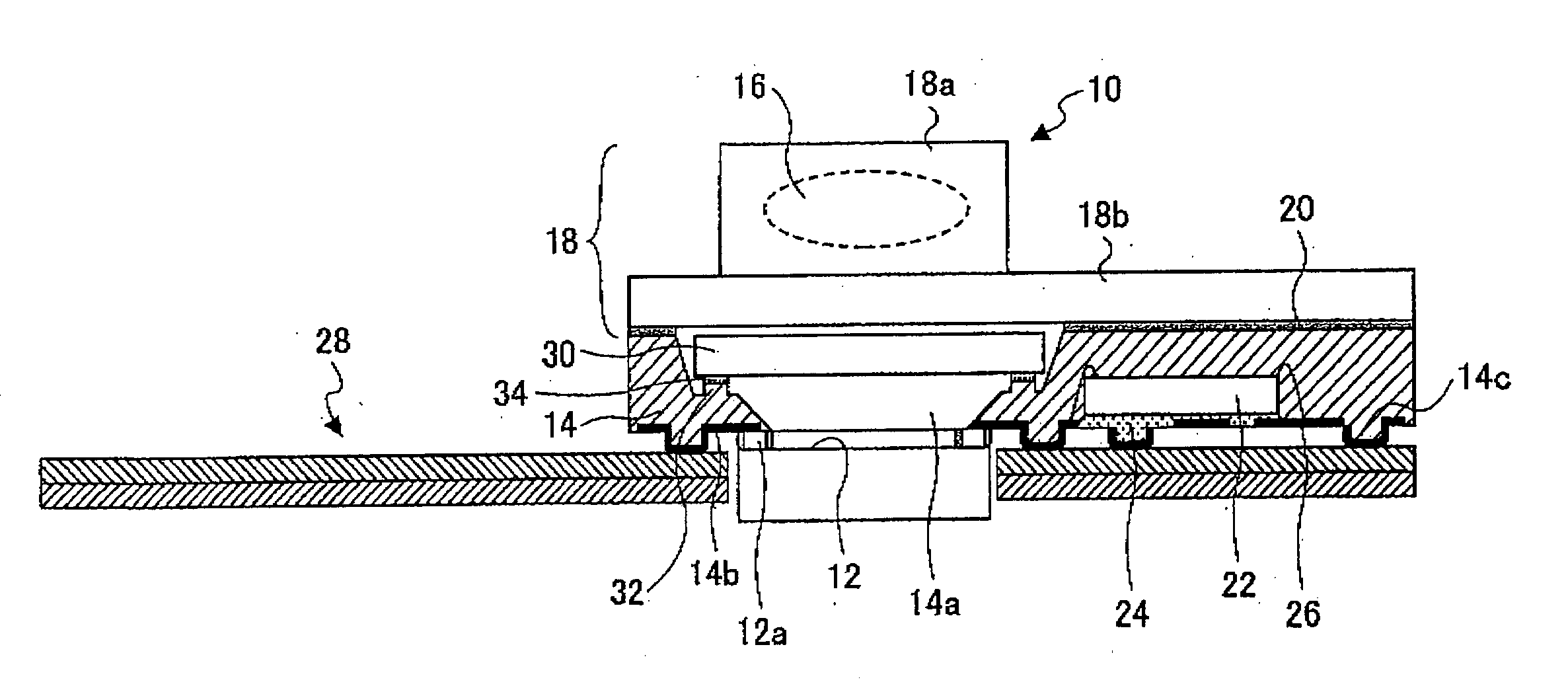
[0060]FIG. 1 is a cross-sectional view of a camera module according to the first embodiment of the present invention. The camera module shown in FIG. 1 comprises a package 14 having an imaging element 12 and a lens unit 18 having an image pickup lens 16 (hereinafter, simply referred to as lens). The package 14 and the lens unit 18 are formed by resin, and the lens unit 18 is fixed to the package 14 via an adhesive 20. It should be noted that, in FIG. 1, the lens unit 18 is not shown as a cross-section.

[0061] The lens unit 18 comprises a mirror-cylinder part 18a in which the lens 16 is accommodated and a base part 18b which is a portion fixed to the package 14. The mirror-cylinder part 18a is provided with a through opening (not shown) so that a light passed through the lens 16 passes through the through opening and travels toward the package 14. As the lens 16, a plastic lens is used gener...

second embodiment

[0083] Next, a description will be given, with reference to FIG. 6 and FIG. 7, of the present invention.

[0084]FIG. 6 and FIG. 7 are cross-sectional views of a camera module according to the second embodiment of the present invention. It should be noted that the lens unit 18 is not indicated as a cross section. In FIG. 6 and FIG. 7, parts that are the same as the parts shown in FIG. 1 are given the same reference numerals, and descriptions thereof will be omitted.

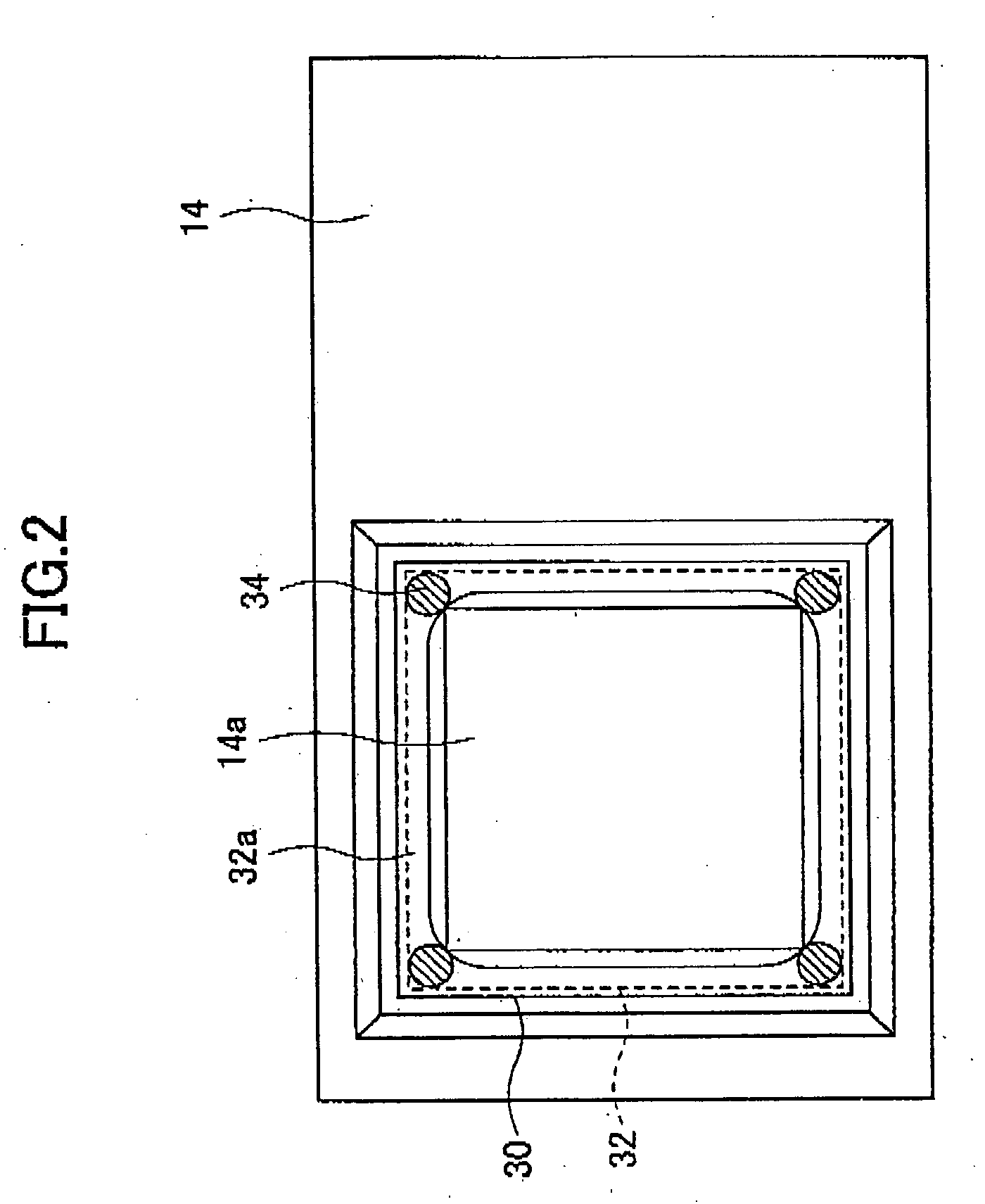
[0085] In the second embodiment of the present invention, minute particles are prevented from separating from the filter 30 by covering a circumferential portion of the filter 30 by a thin film, a resin, etc. The filter 30 shown in FIG. 6 and FIG. 7 is formed with a thin film on the circumferential portion including the side surfaces before it is incorporated into the camera module.

[0086] That is, the filter 30 is subjected to a thin film forming process after it is individualized by being cut out from a large substrate. T...

third embodiment

[0098] Next, a description will be given of the present invention.

[0099] First, a description will be given, with reference to FIG. 10, of a basic structure of a camera module to which the third embodiment of the present invention is applied. FIG. 10 is a cross-sectional view of the cameral module to which the third embodiment of the present invention is applied.

[0100] The camera module 50 shown in FIG. 10 comprises a package 54 having an imaging element 52 and a lens unit 58 having an image pickup lens 56 (hereinafter, simply referred to as lens). The package 54 and the lens unit 58 are formed of resin, and the lens unit 58 is fixed to the package 54 via an adhesive 60. It should be noted that the package 54 is cut out in FIG. 10, and a cross-section thereof is shown.

[0101] The lens unit 18 comprises a mirror-cylinder part 58a in which the lens 56 is accommodated and a base part 58b which is a portion fixed to the package 54. The mirror-cylinder part 58a is provided with a throug...


PUM


Abstract

A camera module includes a module structure constituted by a lens unit to which an image pickup lens is attached and a package to which an imaging element is attached so as to be opposite to the image pickup lens. An optical filter is arranged between the imaging element and the image pickup lens. A portion of a flat surface of the optical filter is fixed to a filter fixing portion via an adhesive. The optical filter is adhered to the filter fixing portion in a state in which an end portion formed by a side surface of the optical filter and the flat surface is in noncontact with the filter fixing portion or the adhesive. Minute particles generated from a cut surface of the optical filter fall outside the filer fixing portion.

Description

CROSS-REFERENCE TO RELATED APPLICATIONS [0001] This application is a U.S. continuation application, filed under 35 USC 111(a) and claiming the benefit under 35 USC 120 and 365(c), of PCT application JP2003 / 012537 filed Sep. 30, 2003. The foregoing application is hereby incorporated herein by reference.BACKGROUND OF THE INVENTION [0002] 1. Field of the Invention [0003] The present invention relates to camera modules and, more specifically, to a camera module in which a light-receiving element and an image pickup lens are unified by packaging. [0004] 2. Description of Related Art [0005] In recent years, a cameral module, in which an imaging element and an image pickup lens are incorporated by being integrated with each other, is used as a camera system containing a signal processing system in an application of mounting to a compact information terminal such as a personal computer or a portable television telephone. [0006] For example, a portable telephone equipped with a small camera ...

Claims


Application Information

Patent Timeline
Patent Type & Authority Applications(United States)
IPC IPC(8): H01L27/00G02B7/02G03B11/00H04N5/225H04N5/335
CPCH04N5/2254H04N5/2253H04N23/54H04N23/55
Inventor ONODERA, MASANORIMORIYA, SUSUMUKOBAYASHI, IZUMIAOKI, HIROSHISAWAHATA, KOJIIRIGUCHI, SHIGEOHONDA, TOSHIYUKIHIRAIWA, KATSURO
Owner FUJITSU SEMICON LTD
Why Eureka
Try Eureka