Wishbone-shaped linkage component and suspension systems incorporating the same

a technology of linkage components and wishbones, which is applied in the direction of interconnection systems, vehicle components, and resilient suspensions, etc., can solve the problems of adding significant weight to the suspension, adding to the overall complexity of the suspension, and expensive manufacturing and assembly

Active Publication Date: 2006-11-02
HENDRICKSON USA L L C
View PDF9 Cites 23 Cited by
  • Summary
  • Abstract
  • Description
  • Claims
  • Application Information

AI Technical Summary

Problems solved by technology

Leaf springs however, are expensive to manufacture and assemble, add significant weight to the suspension, and add to the overall complexity of the suspension when used in conjunction with a stabilizer bar for additional roll stability to achieve a desired vertical spring rate in a given suspension packaging envelope.
When optimizing for ride comfort, a low vertical spring rate is desirable, however roll stability usually suffers especially in leaf spring suspension systems.
Therefore in order to provide the desired ride comfort characteristics, an auxiliary roll stiffness mechanism such as a stabilizer bar must be employed, which adds both cost and weight.
While replacing the pair of leaf springs with a torque box can be readily accomplished in rear, tandem or trailer axles, there are issues unique to the front steering axle that makes incorporating the torque box configuration more difficult in steering axle suspension systems.
First, there are packaging constraints.
This leaves limited space for the torque box, especially considering that the torque box will move up and down in conjunction with the axle.
Another issue relates to the kinematics involved in the steering axle.
Assuming a torque box could be incorporated in a steering axle suspension system, there may be undesirable steering kinetics.
For example, in a leading arm arrangement where the torque box is connected to the steering axle and frame and where the axle is ahead of the torque box linkages, the compliant nature of the bushing and bar arrangement of the torque box could cause an undesirable over-steer effect.

Method used


Image

  • Wishbone-shaped linkage component and suspension systems incorporating the same
  • Wishbone-shaped linkage component and suspension systems incorporating the same
  • Wishbone-shaped linkage component and suspension systems incorporating the same

Examples


Embodiment Construction

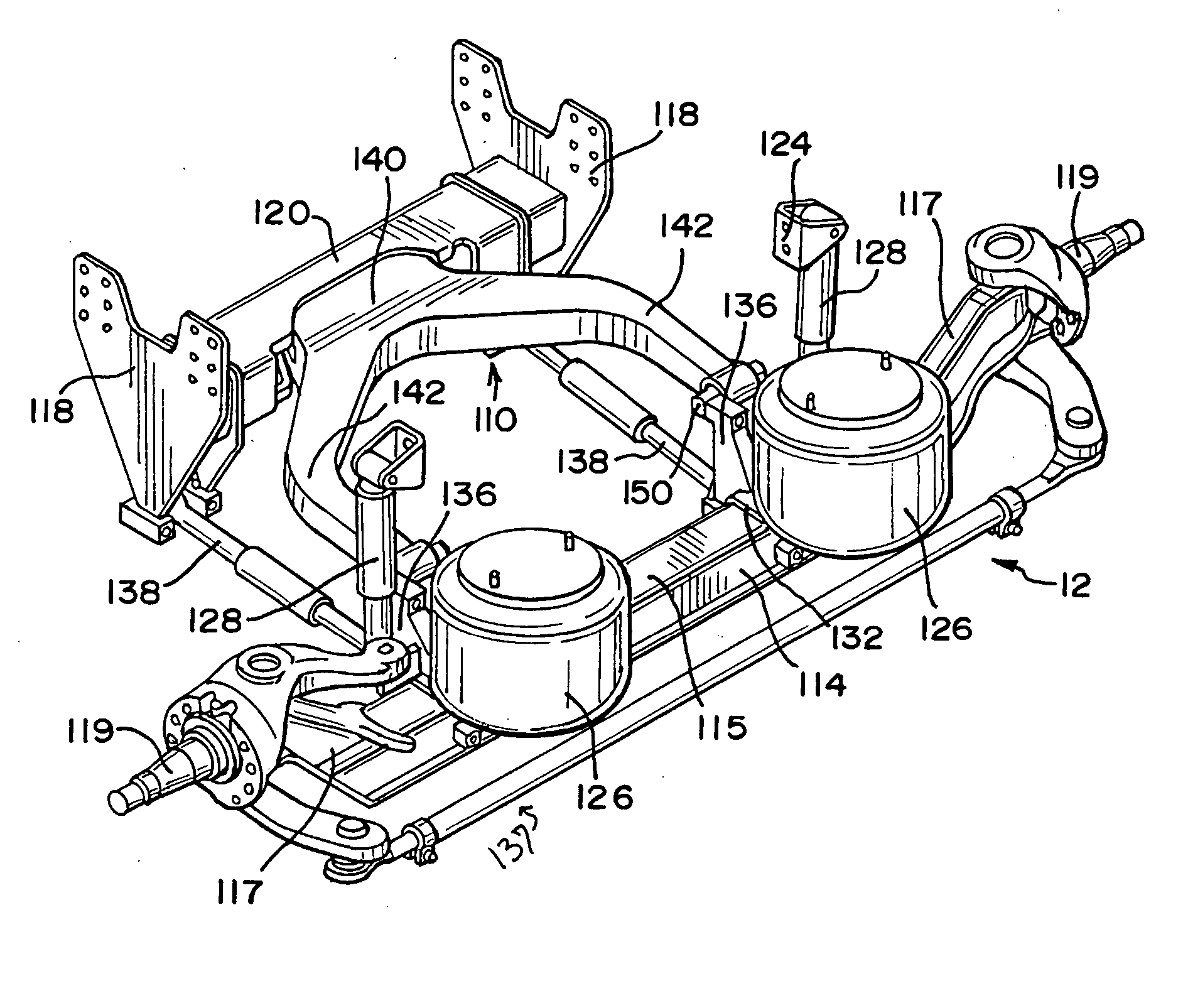
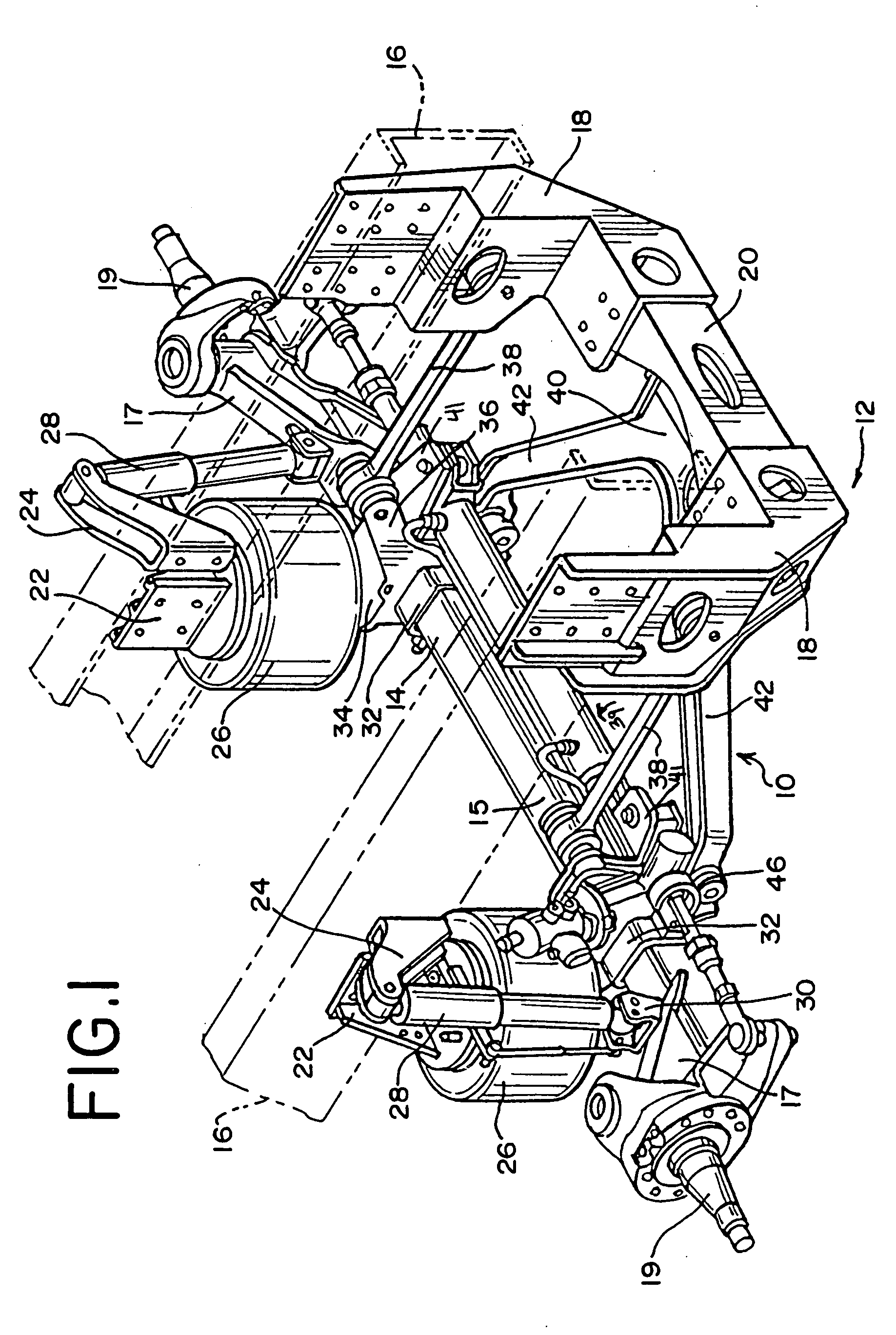
[0018] Referring to the drawings, particularly FIG. 1, a four-point wishbone-shaped linkage 10 is employed in a suspension system 12. As illustrated, the construction of the suspension system 12 on one side of the vehicle is duplicated on the opposite side of the vehicle.

[0019] The suspension system 12 connects the axle 14 to the longitudinally extending vehicle frame members 16 which are on opposite sides of a vehicle chassis. The axle 14 includes a midsection 15 and upwardly inclined portions 17 at opposite ends of the axle 14. Details of the construction of the axle 14 are described in U.S. Pat. No. 6,609,764 (Dudding, et al.), the disclosure of which is hereby incorporated herein by reference. A spindle 19 is used with a steering knuckle for mounting the wheels to the axle 14. The steering knuckle is connected to the axle by a king pin in a known manner. Preferably, the spindle and steering knuckle embody one of the forms described in U.S. Pat. No. 6,616,156 (Dudding, et al.). ...


PUM


Abstract

A four-point wishbone-shaped linkage is disclosed for use in a suspension system. The wishbone-shaped linkage includes a base and two limbs that extend away from the base creating a large mouth open area between the limbs and base. The base includes a bar and bushing assembly extending laterally therethrough. Also disclosed are suspension systems incorporating the four-point wishbone-shaped linkage. The suspension system connects an axle to a vehicle chassis that has a first frame member extending longitudinally on one side of the chassis and a second frame member extending longitudinally on the opposite side of the chassis. The first and second frame hangers are mounted to the first and second frame member, respectively. A cross member connects the first and second frame hangers. In addition to the wishbone-shaped linkage, the suspension system includes first and second air springs connected to first and second frame members respectively and to the axle. A shock absorber is likewise connected to each frame member and axle. Torque rods are also included. One torque rod is pivotally connected to the axle and first frame hanger and a second torque rod is pivotally connected to the axle and second frame hanger. The wishbone-shaped linkage is pivotally connected to the axle and cross member.

Description

BACKGROUND OF THE INVENTION [0001] This invention is directed to vehicle suspension systems, and to linkage suspensions incorporating a unique linkage component. More particularly, the invention is directed to a four-point wishbone-shaped linkage suspension component and suspension systems incorporating a four-point wishbone-shaped linkage. This four-point wishbone-shaped linkage in combination with other suspension system components improves vehicle handling, axle control, ride comfort and cargo protection while minimizing the complexity, package space and weight of the suspension system. [0002] Suspension systems suspend the vehicle chassis over the axle of the vehicle and absorb axle movement caused by the wheels encountering obstacles, holes and uneven road surfaces. Axle movement occurs not only when the wheels encounter obstacles in the road but also during acceleration and braking and during cornering (when the vehicle makes turns). In these situations, it is required that th...

Claims


Application Information

Patent Timeline
Patent Type & Authority Applications(United States)
IPC IPC(8): B60G7/02B60G9/00
CPCB60G7/00B60G9/022B60G2200/315B60G2206/124B60G2204/148B60G2204/41B60G2200/44B60G7/02B60G9/00
Inventor CORTEZ, JEROME LIMROSALES, RODOLFO
Owner HENDRICKSON USA L L C
Why Eureka
Try Eureka