Motor

a technology of electric motors and motors, applied in the field of electric motors, can solve the problems of non-synchronous vibration of low frequency in the rotor, deterioration of the bearing, and non-repeatability of the rotor, so as to reduce the resonance of vibration and synergy superimposition. , the effect of deteriorating the roundness of the sleev

Inactive Publication Date: 2006-11-02
NIDEC CORP
View PDF6 Cites 33 Cited by
  • Summary
  • Abstract
  • Description
  • Claims
  • Application Information

AI Technical Summary

Benefits of technology

[0016] According to the present invention, it is possible to suppress synergy superimposition and synergy superimposition resonance of vibration caused by deterioration of roundness of the sleeve and harmonic vibration caused by number of poles or number of phase. Other objects and effects of the present invention will become apparent in the following detailed description.

Problems solved by technology

Therefore, the characteristics of the bearing are deteriorated, non synchronous vibration of low frequency is generated in a rotor, and NRRO (Non-repeatable Run Out: vibration that is not synchronous with the number of rotations of a rotor when the motor is operated) is deteriorated in some cases.
However, as the motor is reduced in size and thickness, the thickness of the sleeve must be reduced, deterioration of roundness of the sleeve caused by influence of groove formed in the outer side surface is relatively increased, and RRO vibration caused by deterioration of roundness of a sleeve and high order vibration caused in combination of electromagnetic exciting force is prone to be generated.

Method used


Image

  • Motor
  • Motor
  • Motor

Examples


first embodiment

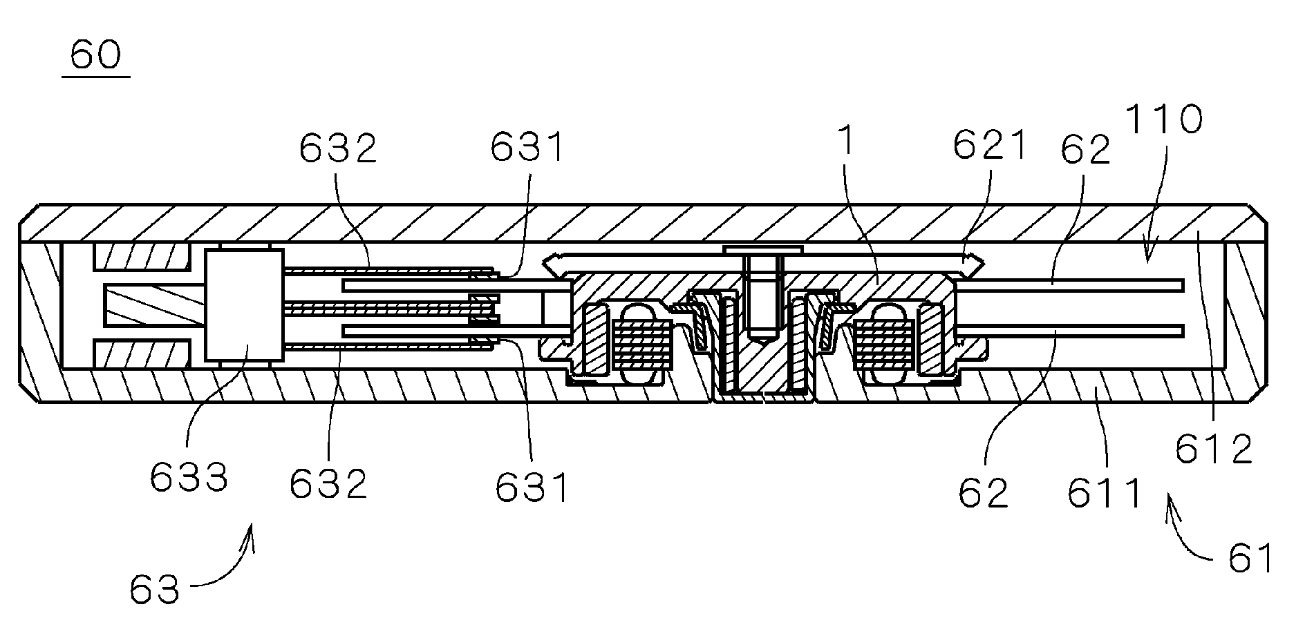
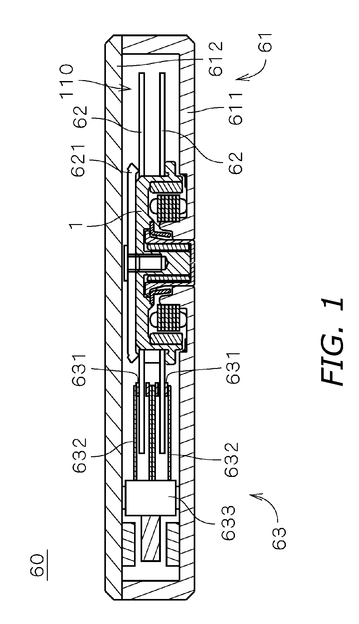
[0024]FIG. 1 shows an internal structure of a recording disk drive 60 having an electric spindle motor 1 (“motor 1,” hereinafter) according to a first embodiment of the invention. The recording disk drive 60 is a hard disk drive. The recording disk drive 60 includes two recording disks 62 for recording information, an access mechanism 63 for writing and (or) reading information into and from the recording disk 62, a motor 1 for holding and rotating the recording disk 62, and a housing 61 for accommodating the recording disk 62, the access mechanism 63 and the motor 1 in an interior space 110.

[0025] As shown in FIG. 1, the housing 61 includes a box-like first housing member 611 having no lid. The first housing member 611 is provided at its upper portion with an opening, and the motor 1 and the access mechanism 63 are mounted on the inside bottom surface of the first housing member 611. The housing 61 also includes a plate-like second housing member 612 which covers the opening of th...

second embodiment

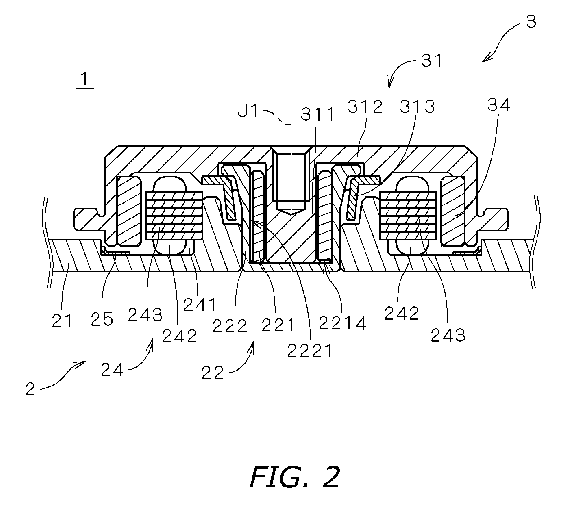
[0052] Next, a motor la of a second embodiment of the present invention will be explained. FIG. 5 is a vertical sectional view showing the motor 1a. As shown in FIG. 5, the motor 1a is substantially the same as the motor 1 shown in FIG. 2 except the structure and the shape of the bearing mechanism utilizing fluid dynamic pressure. The same symbols are added to the following explanation.

[0053] Like the first embodiment, the motor 1a is an electric motor used for rotating a recording disk of a recording disk drive, and is driven by three phase AC. As shown in FIG. 5, the motor 1 a is an outer rotor type motor like the first embodiment, and includes a stator portion 2 which is a fixed assembly, and a rotor portion 3 which is a rotary assembly. The rotor portion 3 is rotatably supported through the bearing mechanism utilizing the fluid dynamic pressure with respect to the stator portion 2 around the center axis J1 of the motor 1a.

[0054] As shown in FIG. 5, in the motor 1a, the shaft 3...


PUM


Abstract

In an electric motor provided with a bearing mechanism utilizing fluid dynamic pressure, it is an object of the invention to restrain synergy superimposition and synergy superimposition resonance of vibration caused by deterioration of roundness of the sleeve and harmonic vibration caused by number of poles or number of phase. In a bearing mechanism which is provided in a motor and which utilizes fluid dynamic pressure of lubricant oil, five straight grooves substantially parallel to the center axis J1 are formed in an outer surface of a sleeve at substantially equal distances from one another in the circumferential direction. The grooves and an inner surface of a sleeve housing form flow paths for circulating the lubricant oil. In the motor, the number of grooves of the sleeve is a relative prime with respect to the number of phase (three phase) of drive current of the motor and the number of poles (eight poles) of the field magnet. With this, it is possible to suppress the synergy superimposition and the synergy superimposition resonance of vibration caused by deterioration of the roundness of sleeve and vibration caused by number of poles of the motor or the number of phase of the drive current.

Description

BACKGROUND OF THE INVENTION [0001] 1. Technical Field [0002] The present invention relates to an electric motor provided with a bearing mechanism utilizing fluid dynamic pressure. [0003] 2. Description of the Related Art [0004] Conventionally, a recording disk drive such as a hard disk drive includes a spindle motor (“motor,” hereinafter) for rotating and driving a recording disk. In recent years, a bearing mechanism utilizing fluid dynamic pressure is employed as one of bearing mechanisms of a motor. In the bearing mechanism utilizing such fluid dynamic pressure, a thrust bearing portion and a radial bearing portion are constituted between a shaft (and a portion connected to the shaft) and a sleeve into which the shaft is inserted. [0005] For example, a housing and a bearing sleeve fixed to an inner peripheral surface of the housing (both are collectively called “sleeve unit,” hereinafter), a shaft member inserted into the sleeve unit, and a thrust member for closing an opening of ...

Claims


Application Information

Patent Timeline
Patent Type & Authority Applications(United States)
IPC IPC(8): H02K7/00H02K5/16
CPCF16C17/026F16C33/107H02K7/085F16F2230/04H02K5/1675F16F15/023
Inventor TAMAOKA, TAKEHITO
Owner NIDEC CORP
Why Eureka
Try Eureka