Electric machine

Inactive Publication Date: 2006-11-02
LUK LAMELLEN & KUPPLUNGSBAU BETEILIGUNGS KG
View PDF5 Cites 12 Cited by
  • Summary
  • Abstract
  • Description
  • Claims
  • Application Information

AI Technical Summary

Benefits of technology

[0017] It may be beneficial when the magnetic disk is designed as an annular disk which is disposed about a carrier part preferably consituted as a shaft or hub member, at least one of the cover plates being nonrotatably connected to the magnetic disk and the carrier part. In response to acceleration and deceleration of the magnetic disk, a portion of the forces of acceleration acting on the magnetic disk are transmitted via the at least one cover plate to the carrier part, thereby reducing the shearing forces in the potting compound correspondingly, in particular in the peripheral zone of the potting compound adjoining the shaft or the hub member. In comparison to an equivalent arrangement without cover plates, this permits a higher torque to be transmitted between the magnetic disk and the carrier part in a manner characterized by long-term stability. The cover plates may be welded, soldered and/or adhesively bonded to the carrier part. The carrier part is preferably made o

Problems solved by technology

Since the magnetic field sensor is positioned radially on the outside with ample clearance, mou

Method used


Image

  • Electric machine
  • Electric machine
  • Electric machine

Examples


Embodiment Construction

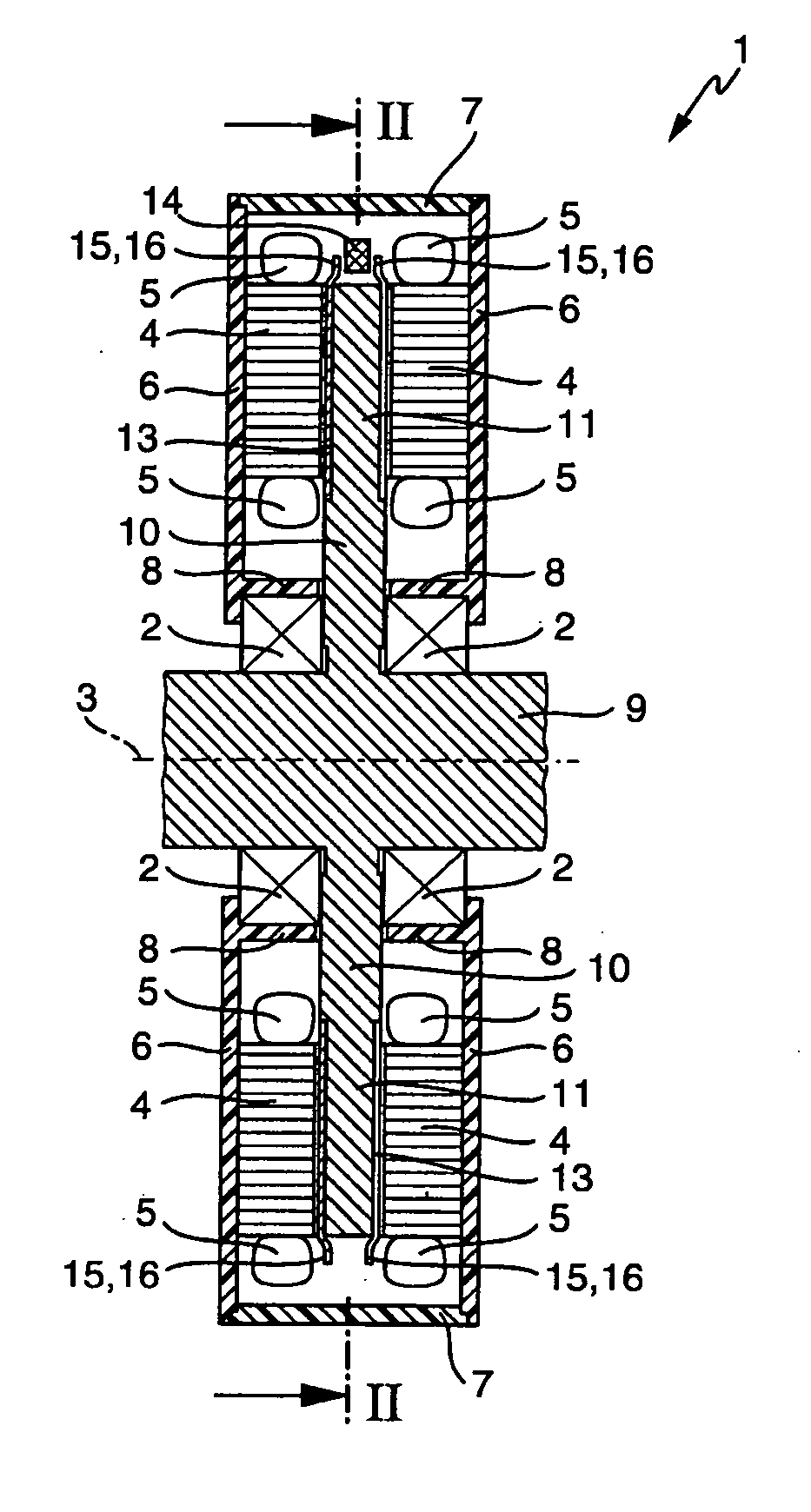
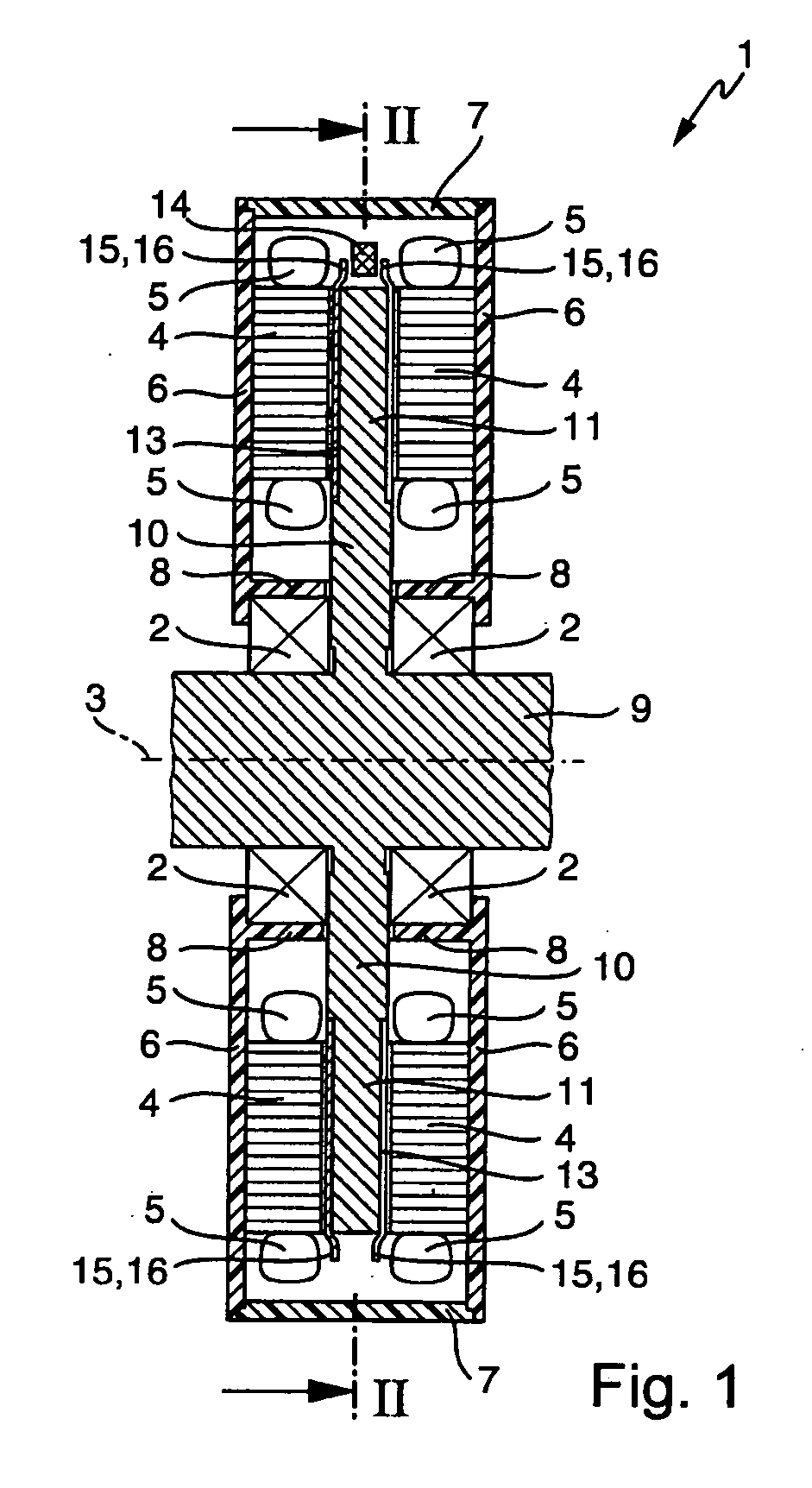
[0032] An electric machine designed as a disk armature, denoted as a whole by 1, has a primary part and a secondary part which are rotationally supported relative to one another by friction bearings or rolling-contact bearings 2 about an imaginary axis of rotation 3. The primary part is designed as a stationary stator and the secondary part as a rotor or rotating armature.

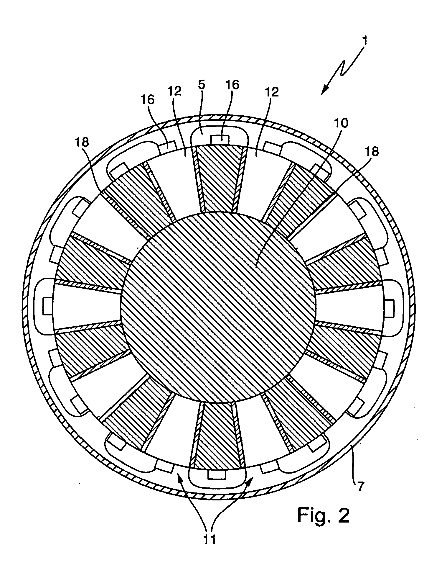
[0033] As is readily discernible in FIG. 1, the primary part has two primary part halves, which are disposed on both sides of the secondary part, enclosing the same therebetween. The secondary part is designed as an intermediate rotor. Each primary part half has one soft magnetic stator core 4, which is disposed about axis of rotation 3 and has slots extending radially to axis of rotation 3 that contain coiled windings of a winding 5. The coiled windings project by their winding heads out of the radially inner and outer ends of the slots.

[0034] Stator core 4 and winding 5 are located in the interior cavity of a h...


PUM


Abstract

An electric machine is designed as a disk armature having a secondary part that is rotationally supported about an axis of rotation relative to a primary part. The secondary part has a magnetic disk, which, on its axial end faces, has a circumferentially extending series of alternating, oppositely magnetized, permanent magnetic poles. The magnetic poles interact magnetically with a winding provided on the primary part across at least one air gap disposed axially between the primary part and the secondary part. To sense the position of the secondary part relative to the primary part, a position transducer is provided having at least one magnetic field sensor for detecting the magnetic poles. The magnetic field sensor is located on the primary part in a region on the stator situated radially outside of the magnetic disk.

Description

[0001] This claims the benefit of German Patent Application No. 10 2005 019 788.4 filed Apr. 28, 2005 and hereby incorporated by reference herein. BACKGROUND [0002] The present invention relates to an electric machine which is designed as a disk armature having a secondary part that is rotationally supported about an axis of rotation relative to a primary part, the secondary part having a magnetic disk, which, on its axial end faces, has a circumferentially extending series of alternating, oppositely magnetized, permanent magnetic poles that interact magnetically with a winding provided on the primary part across at least one air gap disposed axially between the primary part and the secondary part, and having a position transducer for sensing the position of the secondary part relative to the primary part, the position transducer having at least one magnetic field sensor mounted on the primary part, for detecting the magnetic poles. An axis of rotation in this context is understood ...

Claims


Application Information

Patent Timeline
IPC IPC(8): H02K11/00H02K21/12
CPCH02K29/08H02K21/24H02K1/2796
Inventor HILL, WOLFGANG
Owner LUK LAMELLEN & KUPPLUNGSBAU BETEILIGUNGS KG
Why Eureka
Try Eureka