Power switching control device for electric systems

a power switching control and electric system technology, applied in the direction of pulse generators, lighting and heating apparatus, pulse techniques, etc., can solve the problems of electric power supply switching control, electrical power supply likely to be affected by electromagnetic noise, and other electric systems are likely to switch, so as to improve the protection function of erroneous overheating detection and improve the power switching control device

Active Publication Date: 2006-11-02
DENSO CORP
View PDF12 Cites 26 Cited by
  • Summary
  • Abstract
  • Description
  • Claims
  • Application Information

AI Technical Summary

Benefits of technology

[0009] The present invention is directed to improve a power switching control device for electric systems and, more particularly, to inhibit protective function against erroneous overheating detection.
[0010] According to an aspect of the present invention, a power switching control device is constructed with a switching IC and a control circuit IC. The switching IC includes a semiconductor power switching element, which turns on and off supply of current to an electric system. The switching IC further includes a temperature sensor for detecting temperature of the switching element. The control circuit IC is distanced from the switching IC and controls operation of the switching element. The control circuit IC includes an overheat detector circuit for detecting an overheating of the switching IC based on a detection result of the temperature sensor and stops the operation of the switching element upon detection of the overheating. The switching IC and the control circuit IC are connected to each other by bonding wires. A grounding terminal is provided to ground both the switching IC and the control circuit IC. Further, a conductive layer is provided between the control circuit IC and the grounding terminal and joins the control circuit IC to the grounding terminal thereby grounding the control circuit IC.

Problems solved by technology

If the control signal from the engine ECU continues to be high too long due to some abnormality, the IGBT continues to be turned on for a long time in and causes overheating.
This construction is likely to be affected by electromagnetic noise, because the wires have inductive components (L) and capacitive components (c) are formed between the wires and the frame, etc.
Not only the ignition device for engines but also other electric systems, in which electric power supply is switching-controlled, suffer from the same drawback.

Method used


Image

  • Power switching control device for electric systems
  • Power switching control device for electric systems
  • Power switching control device for electric systems

Examples


Embodiment Construction

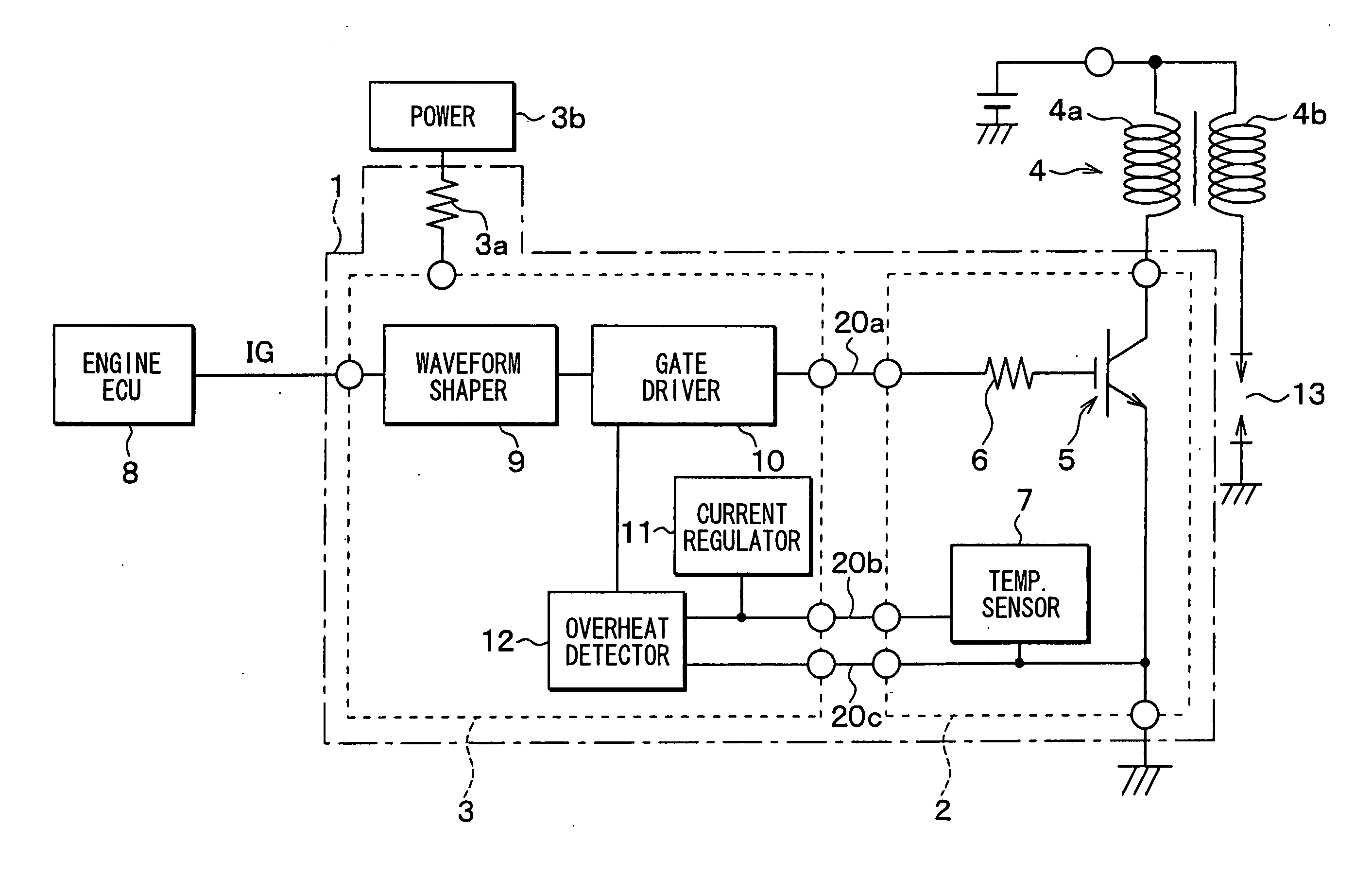
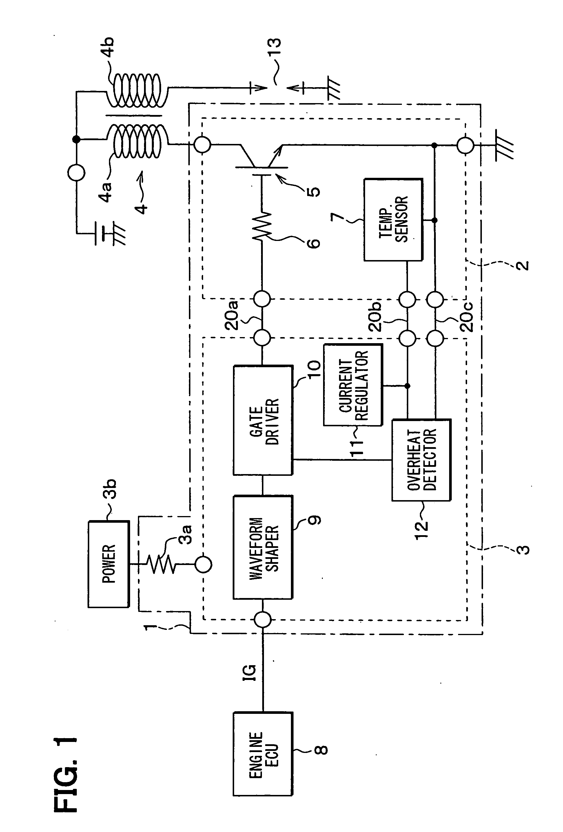
[0018] A power switching control device for electric systems is described with reference to an embodiment, which is constructed as an ignition device 1 for internal combustion engine as shown in FIG. 1.

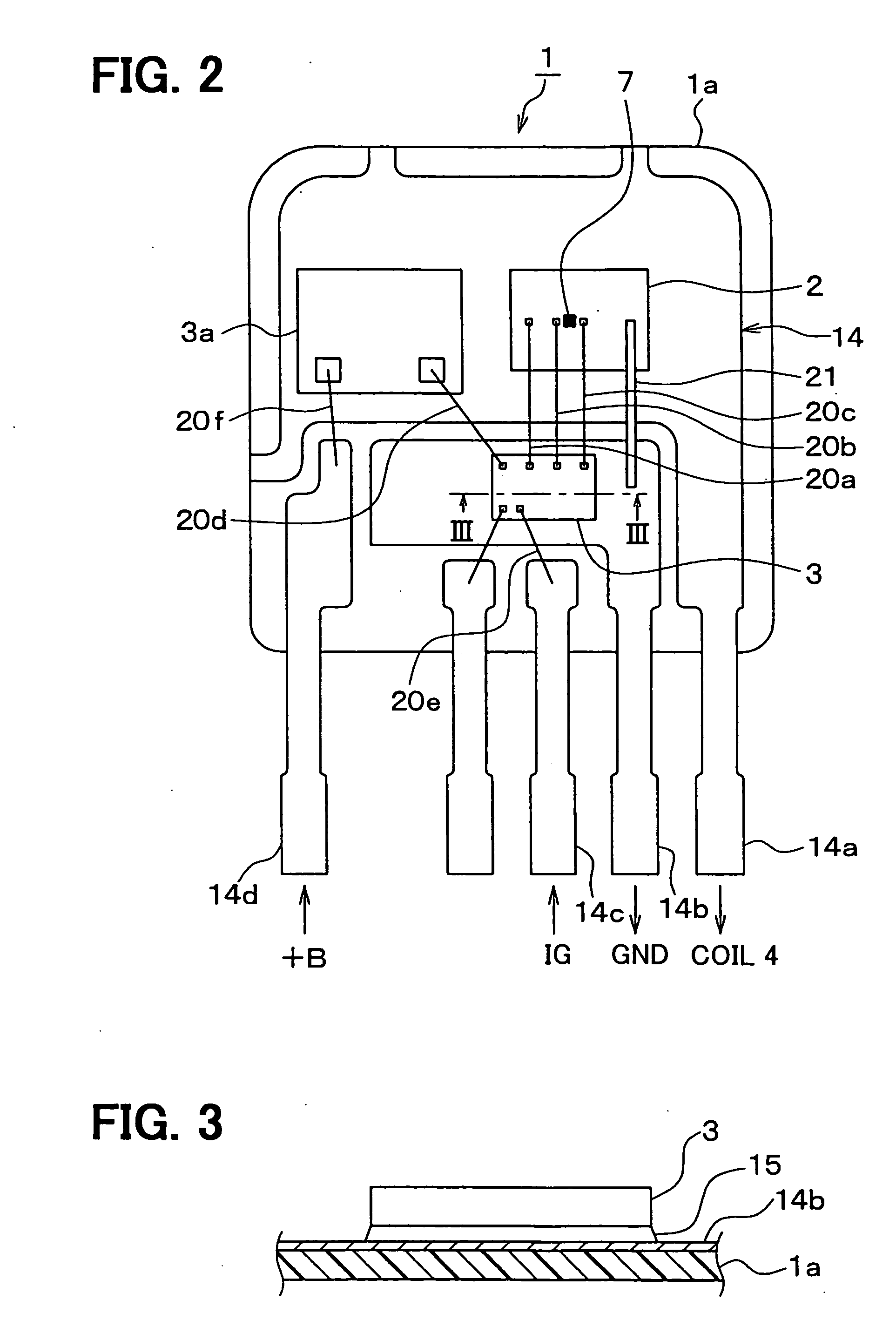
[0019] The ignition device 1 has a switching IC 2 and a control circuit IC 3. The ICs 2 and 3 are formed as separate semiconductor chips from each other and connected to each other through bonding wires 20a, 20b and 20c. The switching IC 2 has an IGBT 5 and a resistor 6 to switching-control current supply to a primary winding 4a of an ignition coil 4. The ignition coil 4 has a secondary winding 4b connected to an engine spark plug 13.

[0020] The gate voltage to the IGBT 5 is controlled by a control signal from a control circuit IC 3 through the resistor 6. When the gate voltage becomes high, the IGBT 5 turns on and supplies current to the primary winding 4a. When the gate voltage becomes low, the IGBT 5 turns off and shuts down the current supply.

[0021] The switching IC 2 further ha...


PUM


Abstract

A power switching control device for electric systems such as an ignition device for internal combustion engines has a control circuit IC and a switching IC. A temperature sensor is provided in the switching IC. The control circuit IC is joined to a grounding terminal through a conductive layer provided therebetween. Thus, the substrate potential of the control circuit IC is stabilized to the ground potential so that the temperature sensor is prohibited to operate erroneously due to electromagnetic noise.

Description

CROSS REFERENCE TO RELATED APPLICATION [0001] This application is based on and incorporates herein by reference Japanese patent application No. 2005-124848 filed on Apr. 22, 2005. FIELD OF THE INVENTION [0002] The present invention relates to a power switching control device for electric systems such as an ignition device for internal combustion engines, the power switching control device having a circuit for restricting overheat of a semiconductor switching element. BACKGROUND OF THE INVENTION [0003] An insulated-gate bipolar transistor (IGBT), which is a semiconductor power switching element, is used in many power switching control devices for electric systems. For instance, it is used in an ignition device for internal combustion engines as disclosed in U.S. Pat. No. 5,664,550 (JP 3,216,972). In this ignition device, the IGBT is turned on and off by a control signal from an electronic control unit for an engine (engine ECU), so that current supply to the primary winding of an ign...

Claims


Application Information

Patent Timeline
Patent Type & Authority Applications(United States)
IPC IPC(8): H03B1/00
CPCF02P3/0552F02P11/06H01L2924/1305H01L2924/13091H01L2924/3011H01L2924/13055H01L2224/73265H01L2224/49175H01L2224/4903H01L2224/48247H01L2224/48137H01L2224/32245H01L24/49H01L2924/00H01L24/48H01L2224/05554H01L2924/00014H01L2924/14H01L2924/181H01L2224/45099H01L2224/05599
Inventor KAWAKITA, HARUO
Owner DENSO CORP
Why Eureka
Try Eureka