Eureka AIR delivers breakthrough ideas for toughest innovation challenges, trusted by R&D personnel around the world.

Piezoelectric element, liquid-jet head and liquid-jet apparatus

Active Publication Date: 2006-11-02
SEIKO EPSON CORP
View PDF18 Cites 6 Cited by
  • Summary
  • Abstract
  • Description
  • Claims
  • Application Information

AI Technical Summary

Benefits of technology

[0009] With the aforementioned conditions taken into consideration, an object of the present invention is to provide a piezoelectric element, which has a high withstand voltage and a longer durability life, a liquid-jet head and a liquid-jet apparatus.

Problems solved by technology

However, according to Japanese Patent Laid-open Official Gazette No. 2004-107181, although the leakage current of the piezoelectric layer can be suppressed, an electric resistivity of the piezoelectric layer is not set.
Accordingly, there has been a problem that the durability of the piezoelectric layer is deteriorated due to an increased leakage current if the electric resistivity is lower.
The problems are similarly present in other piezoelectric elements.

Method used


Image

  • Piezoelectric element, liquid-jet head and liquid-jet apparatus
  • Piezoelectric element, liquid-jet head and liquid-jet apparatus
  • Piezoelectric element, liquid-jet head and liquid-jet apparatus

Examples


first embodiment

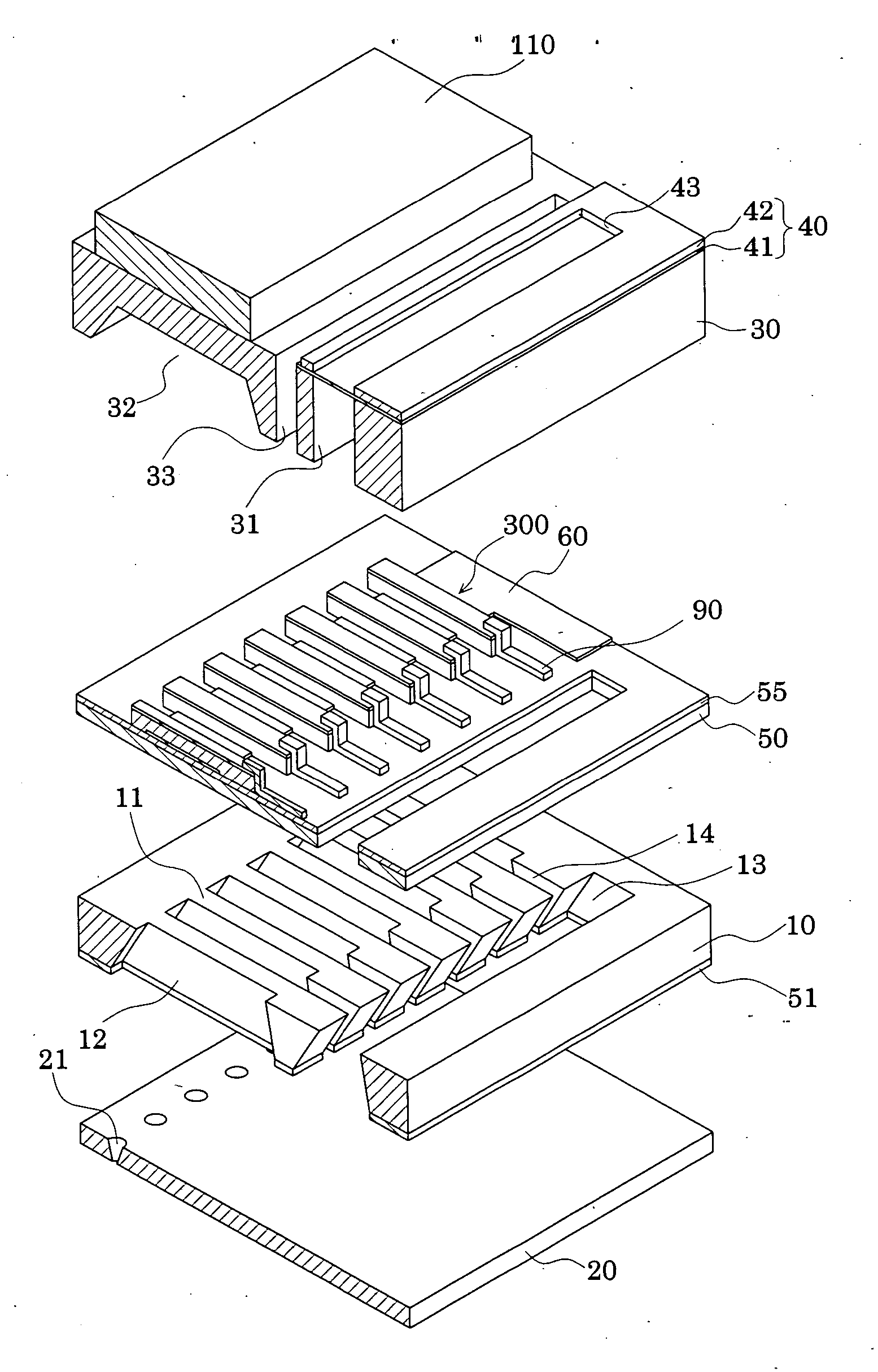
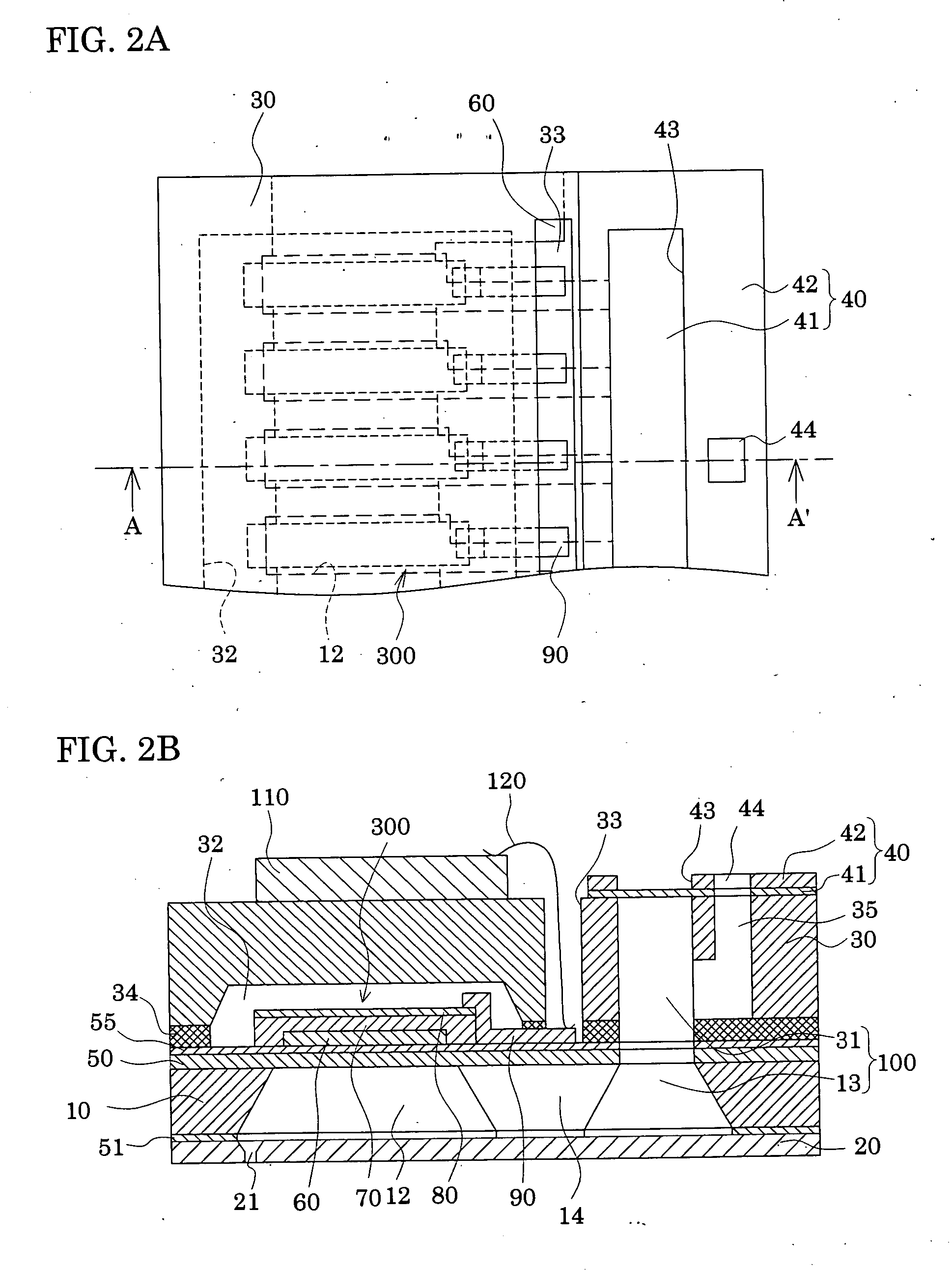
[0035]FIG. 1 is an exploded perspective view of an inkjet recording head according to a first embodiment of the present invention. FIG. 2A is a plan view of the inkjet recording head shown in FIG. 1, and FIG. 2B is a cross-sectional view of the inkjet recording head taken along the A-A′ line of FIG. 2A.

[0036] In the case of this embodiment, a passage-forming substrate 10 is made of a single crystal silicon substrate, as illustrated. An elastic film 50 is formed on one of the two surfaces of the passage-forming substrate 10. The elastic film 50 has a thickness of 0.5 to 2 μm, and is made of silicon dioxide formed beforehand by thermal oxidation.

[0037] In the passage-forming substrate 10, a plurality of pressure generating chambers 12 compartmentalized by compartment walls 11 are arranged side-by-side by means of anisotropically etching the passage-forming substrate 10 from the other side. Outside the pressure generating chambers 12 in the longitudinal direction, a communicating por...


PUM


Abstract

Disclosed are a piezoelectric element, which has a high withstand voltage and a longer durability life, a liquid-jet head and a liquid-jet apparatus. The piezoelectric element includes a lower electrode provided above a substrate, a piezoelectric layer provided above the lower electrode, and an upper electrode provided above the piezoelectric layer, and an electric resistivity of the piezoelectric layer is not lower than 20 MΩ·cm.

Description

[0001] The entire disclosure of Japanese Patent Application Nos. 2005-081729 filed Mar. 22, 2005 and 2005-356706 filed Dec. 9, 2005 is expressly incorporated by reference herein. BACKGROUND OF THE INVENTION [0002] 1. Field of the Invention [0003] The present invention relates to a piezoelectric element including a lower electrode, a piezoelectric layer and an upper electrode. Specifically, the present invention relates to a liquid-jet head which ejects droplets from nozzle orifices, and a piezoelectric element used for a liquid-jet apparatus. [0004] 2. Description of the Prior Art [0005] An inkjet recording head with the following configuration has been put into practical use. In accordance with the configuration, a part of pressure generating chambers communicating with nozzle orifices from which ink droplets are ejected is constructed with a vibration plate. The vibration plate is deformed by piezoelectric elements, and thus ink in each of the pressure generating chambers is press...

Claims


Application Information

Patent Timeline
IPC IPC(8): B41J2/045B41J2/055B41J2/135B41J2/14B41J2/145H01L41/09H01L41/187H01L41/22H01L41/43H02N2/00
CPCB41J2/14233B41J2/161B41J2/1623B41J2/1629B41J2/1632H01L41/318B41J2002/14241B41J2002/14419H01L41/0973H01L41/1876B41J2/1646H10N30/2047H10N30/8554H10N30/078E03D5/00E03D5/10E03D5/09E03D9/08
Inventor LI, XIN-SHAN
Owner SEIKO EPSON CORP
Why Eureka
Eureka Blog
Learn More