Planar light-source device

Inactive Publication Date: 2006-11-02
TRIVALE TECH
View PDF6 Cites 70 Cited by
  • Summary
  • Abstract
  • Description
  • Claims
  • Application Information

AI Technical Summary

Benefits of technology

[0008] In the present invention, a point light source is installed from outside a case, through through-holes formed in the case and a reflection sheet, and a reflector formed on the reflection sheet to correspond to the point light source is slanted with respect to the bottom side of the case, depthward along the through-hole, in a region enclosed by

Problems solved by technology

Accordingly, it has been a problem that, in the case where replacement of the light-source substrate is required, disassembly work and reassembly work of the liquid crystal display module are nec

Method used


Image

  • Planar light-source device
  • Planar light-source device
  • Planar light-source device

Examples


embodiment 1

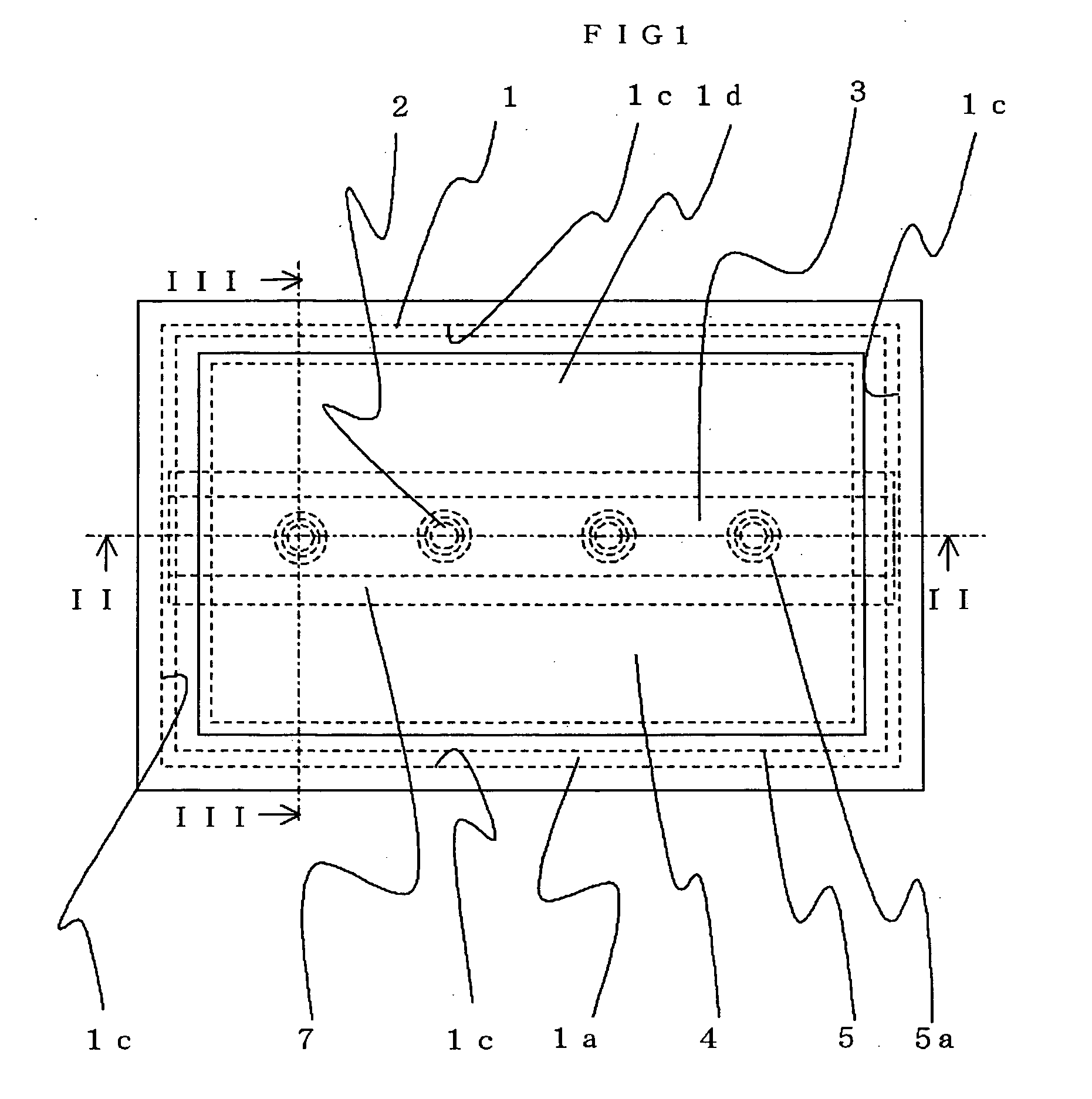
[0024]FIG. 1 is a plan view schematically illustrating the structure of a planar light-source device according to Embodiment 1 of the present invention;

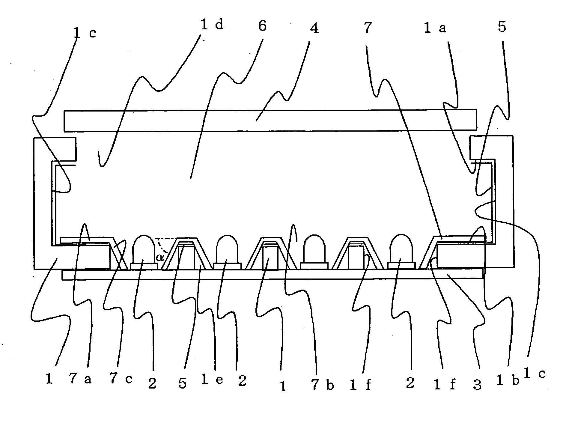
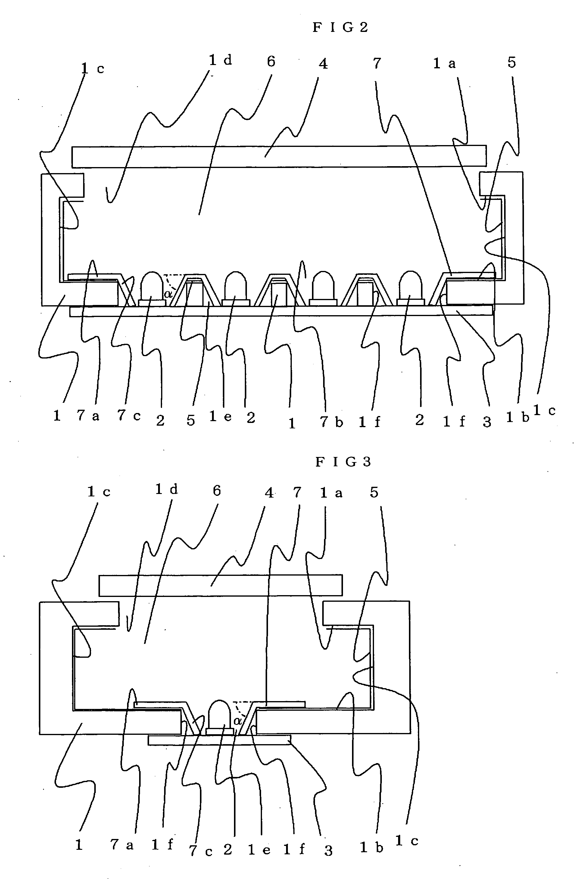
[0025]FIG. 2 is a partial cross-sectional view, taken along the line II-II indicated by the arrows, of the planar light-source device illustrated in FIG. 1;

[0026]FIG. 3 is a partial cross-sectional view, taken along the line III-III indicated by the arrows, of the planar light-source device illustrated in FIG. 1;

[0027]FIG. 4(a) is a plan view illustrating another shape of an oblique portion of a reflector;

[0028]FIG. 4(b) is a partial cross-sectional view, taken along the line A-A indicated by the arrows, of the oblique portion illustrated in FIG. 4(a);

[0029]FIG. 4(c) is a partial cross-sectional view, taken along the line B-B indicated by the arrows, of the oblique portion illustrated in FIG. 4(a);

[0030]FIG. 5(a) is a plan view illustrating another shape of an oblique portion of a reflector;

[0031]FIG. 5(b) is a partial cross-s...

embodiment 2

[0082]FIG. 10 is a plan view schematically illustrating the structure of a planar light-source device according to Embodiment 2 of the present invention; FIG. 11 is a partial cross-sectional view, taken along the line XI-XI indicated by the arrows, of the planar light-source device illustrated in FIG. 10; FIG. 12 is a plan view schematically illustrating the structure of another planar light-source device according to the present invention; FIG. 13 is a partial cross-sectional view, taken along the line XIII-XIII indicated by the arrows, of the planar light-source device illustrated in FIG. 12; FIG. 14 is a plan view schematically illustrating the structure of further another planar light-source device according to the present invention; and FIG. 15 is a partial cross-sectional view, taken along the line XV-XV indicated by the arrows, of the planar light-source device illustrated in FIG. 14. In FIGS. 10 to 15, the same reference marks as those in FIGS. 1 to 9 designate the same or e...


PUM


Abstract

A planar light-source device is obtained in which, in the space between a point light source and the peripheral portion of a through-hole in a case, rays that leak into or are absorbed into a space outside a hollow region can be reduced, whereby the number of rays that propagate into the hollow region can be increased. A point light source is installed from outside a case, through through-holes formed in the case and a reflection sheet, and a reflector formed on the reflection sheet to correspond to the point light source is slanted with respect to the bottom side of the case, depthward along the through-hole, in a region enclosed by the peripheral portion of the through-hole of the case and by the point light source.

Description

BACKGROUND OF THE INVENTION [0001] 1. Field of the Invention [0002] The present invention relates to a planar light-source device having a reflector for efficiently guiding light from a point light source into a case. [0003] 2. Description of the Prior Art [0004] In a conventional planar light-source device, by making part of the light-source side of a light-source substrate having light sources facing a transverse end face of a light guide plate that is provided on the rear side of a liquid-crystal display panel contact the rear side of the light guide plate, and making the side, opposite to the light-source side, of the light-source substrate contact a substrate support portion of a case, the light-source substrate is interposed between the light guide plate and the substrate support portion (e.g., refer to Japanese Laid-Open Patent No. 2002-107721, p 3, 20th line in left column to 34th line in left column and FIG. 1). SUMMARY OF THE INVENTION [0005] In the conventional planar lig...

Claims


Application Information

Patent Timeline
IPC IPC(8): F21V7/04F21V1/00
CPCG02F1/133605G02F1/133603
Inventor SAKAMOTO, TAKUYAMORI, AKIHIRO
Owner TRIVALE TECH
Why Eureka
Try Eureka