Hybrid backlight apparatus

a backlight apparatus and hybrid technology, applied in lighting and heating apparatus, electrophonic musical instruments, instruments, etc., can solve the problems of narrow color expression range, lowering luminance, and reducing the overall output of light, so as to effectively adjust the color temperature of white light and not decrease the amount of light. , the effect of widening the color expression rang

Inactive Publication Date: 2006-11-02
SAMSUNG ELECTRO MECHANICS CO LTD
View PDF6 Cites 31 Cited by
  • Summary
  • Abstract
  • Description
  • Claims
  • Application Information

AI Technical Summary

Benefits of technology

[0018] The present invention has been made to solve the foregoing problems of the prior art and it is therefore an object of the present invention to provide a hybrid backlight ap

Problems solved by technology

However, the prior art fluorescent lamp-based backlight apparatus 10 has several problems as explained hereinbelow.
In addition, as the output light of the fluorescent lamp is filtered, undesired stray light may be mixed together due to the w

Method used


Image

  • Hybrid backlight apparatus
  • Hybrid backlight apparatus
  • Hybrid backlight apparatus

Examples


first embodiment

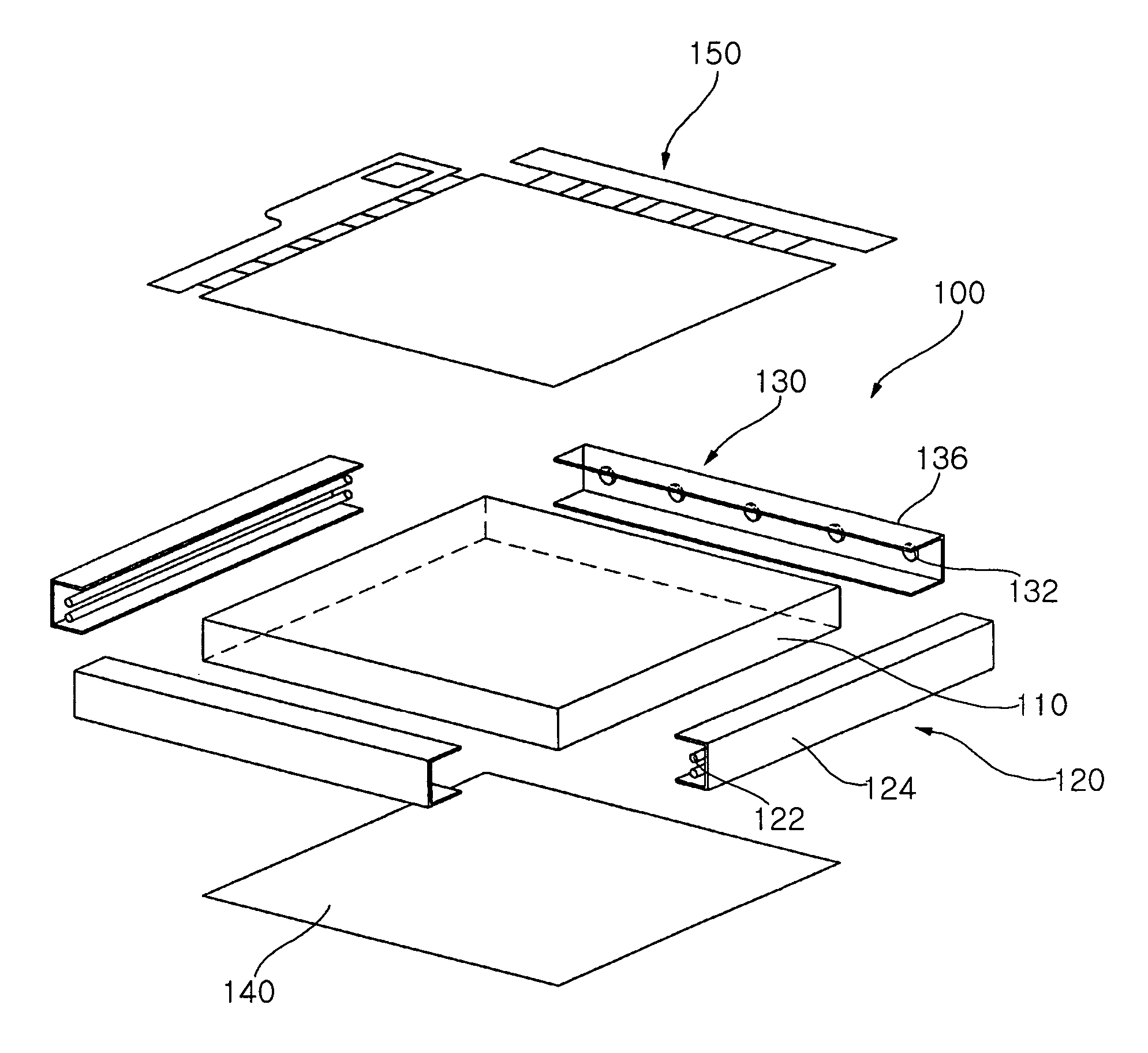
[0040]FIG. 4 is a plan view showing an exploded constitution of a hybrid backlight apparatus according to the present invention, and FIG. 5 is an exploded perspective view of the hybrid backlight apparatus in FIG. 4 together with an LCD panel.

[0041] As shown in FIGS. 4 and 5, the backlight apparatus 100 according to the present invention adopts an edge irradiation method, and includes a light guide plate 110 made of transparent resin, a pair of white light sources 120 for the main light source disposed at a pair of opposed edges of the light guide plate 110 and a pair of monochromatic light sources 130 for a supplementary light source disposed at the other pair of opposed edges.

[0042] The light guide plate 110 is a plate member having a predetermined thickness, composed of transparent acryl, Polymethylmethacrylate (PMMA), plastic or glass.

[0043] Each white light source 120 includes a lamp 122 and a reflection mirror 124 which reflects light from the lamp 122 into the light guide p...

second embodiment

[0069]FIG. 9 is an exploded perspective view illustrating an overall constitution of a hybrid backlight apparatus according to the present invention, and FIG. 10 is a sectional view of the hybrid backlight apparatus of FIG. 9.

[0070] With reference to FIGS. 9 and 10, the hybrid backlight apparatus 200 according to the second embodiment of the present invention is a direct illumination type, including a reflection plate 210, a plurality of white light sources 220 disposed above the reflection plate 210 and monochromatic light sources 230 disposed between the white light sources 220.

[0071] The backlight apparatus 200 further includes a housing H as a space for receiving the above constituents therein. The housing H includes a bottom surface 202 for supporting the reflection plate 210 and side walls 204 for supporting the white light sources 220. The inner surface of the side wall 204 may have a reflection surface so as to reflect the light generated from the white light source 220 and...


PUM


Abstract

The present invention relates to a backlight apparatus for a Liquid Crystal Display. The backlight apparatus includes a main light source for generating white light and a monochromatic light source for generating monochromatic light to compensate the color temperature of the white light. The backlight further includes a light mixing region for mixing the white light with the monochromatic light to form mixed light with compensated color temperature and a reflection plate disposed underneath the light mixing region. The invention provides the monochromatic light source in addition to the fluorescent lamp, widening the color expression range and effectively adjusting the color temperature, thereby enabling natural color expression.

Description

CLAIM OF PRIORITY [0001] This application claims the benefit of Korean Patent Application No. 2005-36884 filed on May 2, 2005, in the Korean Intellectual Property Office, the disclosure of which is incorporated herein by reference. BACKGROUND OF THE INVENTION [0002] 1. Field of the Invention [0003] The present invention relates to a backlight apparatus for a Liquid Crystal Display (LCD), and more particularly, to a hybrid backlight apparatus for an LCD, in which a monochromatic light source is added to a fluorescent lamp to widen a color expression range and effectively adjust a color temperature, thereby enabling natural color expression. [0004] 2. Description of the Related Art [0005] In general, a Liquid Crystal Display (LCD) includes a pair of glass plates and liquid crystal injected into each pixel between the glass plates. The LCD displays an image as the arrangement of the liquid crystal molecule of each pixel is altered when supply voltage is applied to the electrodes of the...

Claims


Application Information

Patent Timeline
IPC IPC(8): G01D11/28
CPCG02B6/0068G02F1/133609G09B15/08G10C3/12G10F1/02G10H1/34
Inventor JEONG, HOKAWAI, KIYOYUKIKIM, JIN
Owner SAMSUNG ELECTRO MECHANICS CO LTD
Why Eureka
Try Eureka