Vibrating device, jet flow generating apparatus, and electronic apparatus

a jet flow generating apparatus and vibration technology, applied in the direction of dynamo-electric machines, dynamo-electric devices, instruments, etc., can solve the problems of vibration not being efficiently transmitted to the gas, high cooling ability of the device, and large amount of gas discharge, so as to achieve the effect of suppressing the generation of nois

Inactive Publication Date: 2006-11-02
SONY CORP
View PDF2 Cites 7 Cited by
  • Summary
  • Abstract
  • Description
  • Claims
  • Application Information

AI Technical Summary

Benefits of technology

[0011] Since the driving mechanism according to an embodiment of the present invention includes a voice coil body configured to prevent the voice coil body from coming into contact with the magnetic circuit member when the vibrating plate is vibrating, unwanted noise caused by the voice coil body contacting the magnetic circuit member is suppressed. Accordingly, noise can be suppressed, for example, while maintaining a predetermined gas discharge amount without reducing the frequency and amplitude of the vibrating plate.
[0017] In particular, it is desirable that, when the third length R is in the range of 10 to 40 mm, the predetermined distance d be in the range of 0 to 20 mm or 0 to 10 mm. For example, when a portable apparatus is to be provided as the electronic apparatus including the vibrating device, the most practical third length R for the portable apparatus is in the range of 10 to 40 mm. More desirable, the third length R is in the range of 15 to 35 mm. In this case, when the above-mentioned formula is applied, the distance d is in the range of 0 to 20 mm or 0 to 10 mm. When distance d equals zero, the supporting member will support the vibrating plate on the plane where the magnetic plate is disposed, reducing the thickness of the vibrating device.
[0021] According to an embodiment of the present invention, the voice coil body is attached to the vibrating plate at a fourth position that is a position different from the second position along the vibrating direction. The fourth position is closer to the magnet than the second position or the fourth position is further from the magnet than the second position. In such case, the vibrating plate does not have to be flat and may be cone-shaped or a side plate may be provided. By providing a three-dimensional vibrating plate, instead of a flat vibrating plate, the rigidity of the vibrating plate is increased, and bending of the vibrating plate can be suppressed to enable efficient vibration. As a result, the gas discharge efficiency is increased. In particular, if the fourth position is provided opposite to the first position in the vibration direction relative to the second position, the thickness of the vibrating device can be reduced.
[0023] According to an embodiment of the present invention, the vibrating plate includes a first flat plate supported by the supporting member, and a second flat plate attached to the voice coil body and substantially parallel to the first flat plate. In this case, also, the vibrating plate is three-dimensional, instead of being flat, and the rigidity of the vibrating plate can be increased.
[0025] According to an embodiment of the present invention, the driving mechanism includes a vibrating plate that has a side plate supported by a supporting member and a flat plate attached to a voice coil body. The driving mechanism includes an electric supply line that is connected to the voice coil body and disposed along the first flat plate and the second flat plate. According to such a configuration, the vibrating plate and the electric supply line move as a unit, preventing the electric supply line from breaking when the vibrating plate vibrates.
[0032] As described above, according to an embodiment of the present invention, generation of noise can be suppressed without reducing the gas discharge amount.

Problems solved by technology

However, when the amount of heat generated by the heat-generating body is great, a device having a high cooling ability, i.e., a device having a great gas discharge amount, will be required.
However, if the amplitude is increased too much, the vibrating plate will bend, and vibration will not be efficiently transmitted to the gas.
As a result, extreme noise will be generated.

Method used


Image

  • Vibrating device, jet flow generating apparatus, and electronic apparatus
  • Vibrating device, jet flow generating apparatus, and electronic apparatus
  • Vibrating device, jet flow generating apparatus, and electronic apparatus

Examples


embodiments

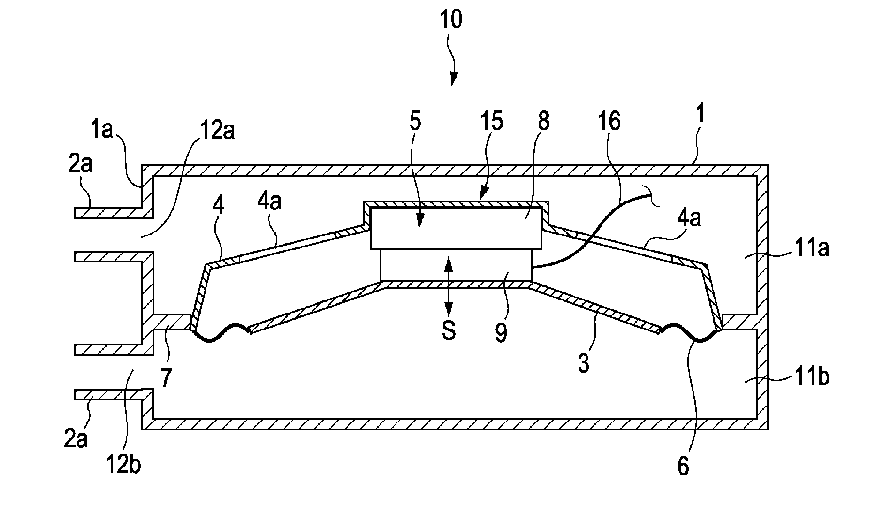
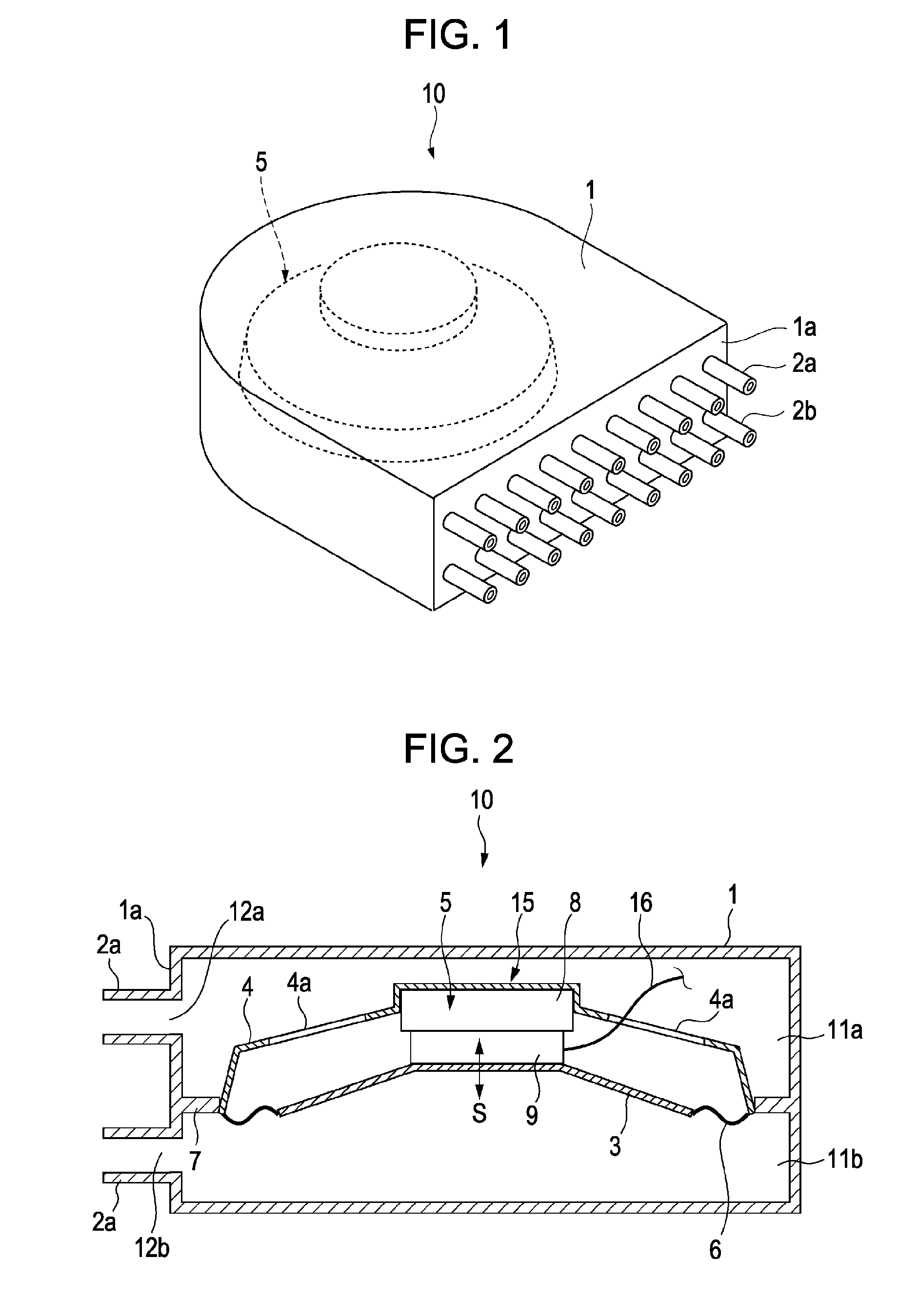
[0063]FIG. 1 illustrates a perspective view of a jet flow generating apparatus according to a first embodiment of the present invention. FIG. 2 illustrates a cross-sectional view of the jet flow generating apparatus shown in FIG. 1.

[0064] A jet flow generating apparatus 10 includes a chassis 1 whose rear part is rounded and a vibrating device 15 disposed inside the chassis 1. On a front surface la of the chassis 1, rows of nozzles 2a and 2b are provided. As shown in FIG. 2, the inside of the chassis 1 is divided into an upper chamber 11a and a lower chamber 11b by an attachment part 7 to which the vibrating device 15 is attached. On the front surface 1a of the chassis 1, where the nozzles 2a and 2b are provided, openings 12a and 12b are formed at positions corresponding to the nozzles 2a and 2b, respectively. In this way, the upper chamber 11a and the lower chamber 11b communicate with the outside the chassis 1. The upper chamber 11a and the lower chamber 11b have substantially the...


PUM


Abstract

A vibrating device configured to vibrate a gas inside a chassis to discharge the gas in a pulsating flow through an opening formed in the chassis includes a frame, a vibrating plate, a supporting member that is attached to the frame and that is configured to support the vibrating plate in a manner such that the vibrating plate is vibratable, and a driving mechanism that is configured to drive the vibrating plate and that includes a magnetic circuit member attached to the frame and a voice coil body attached to the vibrating plate. The voice coil body is configured to prevent the voice coil body from contacting the magnetic circuit member when the vibrating plate is vibrating and is movable by means of a magnetic field generated by the magnetic circuit member.

Description

CROSS REFERENCES TO RELATED APPLICATIONS [0001] The present invention contains subject matter related to Japanese Patent Application JP 2005-130309 filed in the Japanese Patent Office on Apr. 27, 2005, the entire contents of which are incorporated herein by reference. BACKGROUND OF THE INVENTION [0002] 1. Field of the Invention [0003] The present invention relates to a vibrating device configured to apply vibration to a gas to generate a jet flow of the gas and, more specifically, relates to a jet flow generating apparatus including the vibrating device and an electronic apparatus including the jet flow generating apparatus. [0004] 2. Description of the Related Art [0005] A known problem accompanying the advancement of the performance of personal computers (PCs) is an increase in the amount of heat dispersed from heat-generating bodies, such as integrated circuits (ICs). Various technologies for dispersing heat have been proposed, and products employing such technologies have been p...

Claims


Application Information

Patent Timeline
Patent Type & Authority Applications(United States)
IPC IPC(8): H04R1/00
CPCH02K33/18G06F1/00G06F1/20H01L23/467
Inventor ISHIKAWA, HIROICHI
Owner SONY CORP
Why Eureka
Try Eureka