
Vibration reduction moving coil speaker

Inactive Publication Date: 2020-04-23
GM GLOBAL TECH OPERATIONS LLC
View PDF0 Cites 0 Cited by
  • Summary
  • Abstract
  • Description
  • Claims
  • Application Information

AI Technical Summary

Benefits of technology

The invention aims to reduce or eliminate unwanted noise and vibrations caused by sound waves produced by speakers. The technical effect of the invention is to minimize or eliminate the reactionary forces that speakers endure during operation, thereby reducing or eliminating mechanical vibrations and noise.

Problems solved by technology

The sound waves produced by the cone of the speaker oftentimes impart reactionary forces on the speaker itself, which may generate mechanical vibrations in the speaker.
In turn, these mechanical vibrations may be transferred to a supporting structure, frame, or enclosure of the speaker, and may produce unwanted noise, e.g., buzz, squeak, or rattle.

Method used


Image

  • Vibration reduction moving coil speaker
  • Vibration reduction moving coil speaker
  • Vibration reduction moving coil speaker

Examples


Embodiment Construction

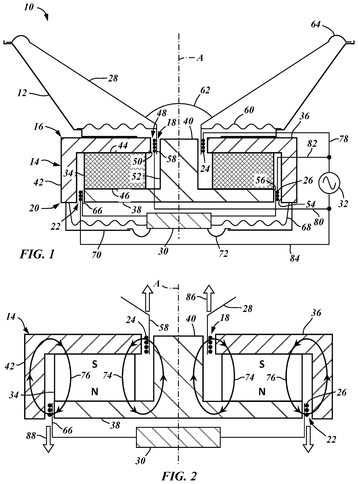
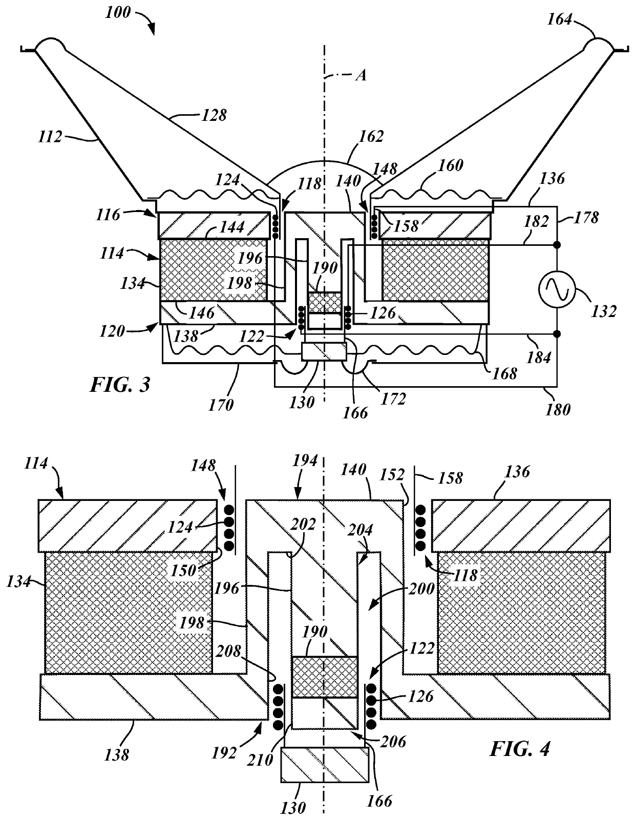
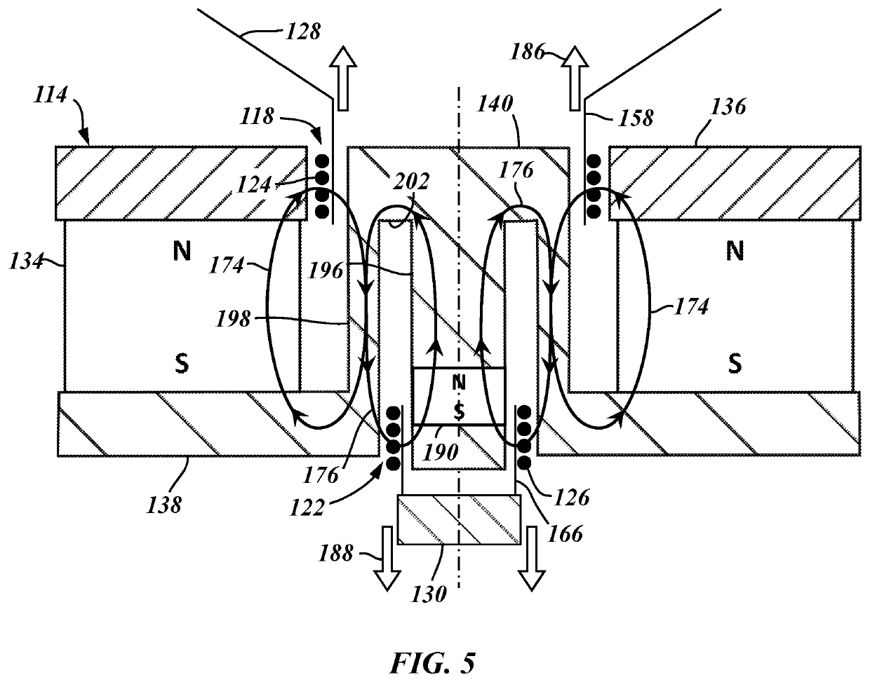
[0027]The moving coil speakers described herein include a cone coupled to and driven by a voice coil and a mass coupled to and driven by a secondary coil. The cone and the mass are driven in opposite axial directions during operation of the speaker such that the axial movement of the cone is counterbalanced by the axial movement of the mass, which reduces or eliminates the net force imparted on the speaker during operation thereof. Reducing or eliminating the net force imparted on the speaker during operation can, in turn, reduce or eliminate the generation of mechanical vibrations in the speaker and the transfer of such vibrations to support structures fixedly attached thereto.

[0028]FIGS. 1 and 2 illustrate a moving coil speaker 10, in accordance with one or more embodiments of the present disclosure. The speaker 10 has a central axis A and includes a rigid frame 12, a magnet assembly 14 having a front end 16 that defines a first annular gap 18 and an opposite back end 20 that defi...


PUM


Abstract

A moving coil speaker may comprise a frame, a magnet assembly fixedly mounted to the frame and having a central axis, first and second annular gaps defined by the magnet assembly and concentrically disposed about the central axis, a voice coil at least partially received within the first annular gap, a cone coupled to and driven by the voice coil, a secondary coil at least partially received within the second annular gap, and a mass coupled to and driven by the secondary coil. When variable electrical audio signals are sent from an audio signal source respectively through the voice coil and the secondary coil, the coils and their respectively associated cone and mass reciprocate back and forth in opposite axial directions, with the reciprocal movement of the cone being counterbalanced by the reciprocal movement of the mass.

Description

INTRODUCTION[0001]A moving coil speaker typically includes a diaphragm or cone attached to a coil of wire (referred to as a voice coil) suspended in a narrow annular gap in a magnetic field generated by a permanent magnet. When variable electrical audio signals, in the form of alternating electric currents, are applied to the voice coil, a variable magnetic field is generated around the voice coil that interacts with the magnetic field generated by the permanent magnet and forces the voice coil to reciprocate back and forth within the annular gap. The back and forth movement of the voice coil is transferred to the attached cone, which is driven outward and pulled inward under the control of the electrical audio signals applied to the voice coil. This back and forth movement of the cone pushes or pulls surrounding air, which translates the variable electrical audio signals into audible sound waves.[0002]The sound waves produced by the cone of the speaker oftentimes impart reactionary...

Claims


Application Information

Patent Timeline
IPC IPC(8): H04R9/06H04R9/04H04R9/02H04R7/12
CPCH04R9/046H04R2400/11H04R9/025H04R7/127H04R9/06H04R9/02H04R1/2869
Inventor SINGER, IAN R.ALYASSIRY, DARGHAM
Owner GM GLOBAL TECH OPERATIONS LLC
Learn More